Understanding von Neumann Stored Program Computer Architecture
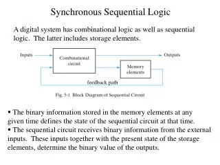
This lecture provides an in-depth overview of the von Neumann architecture, which defines a stored-program computer where programs and data reside in the same memory. Key components such as the Control Unit, Processing Unit, and buses are discussed, along with the sequential execution of instructions. Important signals, registers, and the functioning of the Arithmetic/Logic Unit (ALU) are explored. Challenges such as the "von Neumann bottleneck" are also addressed, highlighting its impact on data retrieval and processing efficiency.

Understanding von Neumann Stored Program Computer Architecture
E N D
Presentation Transcript
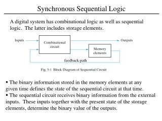
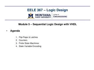
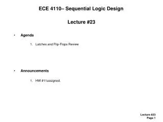
ECE 4110– Sequential Logic Design Lecture #30 • Agenda • von Neumann Stored Program Computer Architecture • Announcements • N/A.
von Neumann Computer • von Neumann Stored Program Computer- "Stored Program" means the HW is designed to execute a set of pre-defined instructions- the program and data reside in a storage unit (i.e., memory)- to change the functionality of the computer, the program is changed (instead of the HW)- John von Neumann was a mathematician who described a computer architecture where the instructions and data reside in the same memory- this implies sequential execution- it is simple from the standpoint of state machine timing- the drawback is the "von Neumann bottleneck" in getting data into and out of memory in order for the computer to run- this architecture is what we are using in the labs on the Freescale microcontrollers • (in ECE 3120, ECE4140)
von Neumann Computer • Block Diagram of von Neumann Computer
von Neumann Computer • Block Diagram of the Central Processing Unit (CPU)
von Neumann Computer • Central Processing Unit (CPU)- the CPU consists of: 1) Control Unit - the state machine that directs the execution of instructions. - for a given Opcode, the state machine traverses a specific path within its state diagram - also called the "Sequence Controller" or "Sequencer" 2) Processing Unit - contains all of the registers and ALU that hold and manipulate data - memory signals (data/address) coming into/out-of this unit 3) Control Signals - signals sent to processing unit from the control unit - direct data flow - load data into registers - select ALU operation - manage memory access signals 4) Test Signals - signals sent to control unit from the processing unit - results of operations that effect state machine flow
von Neumann Computer • Processing Unit - let's start with the registers within the processing unitInstruction Registers (IR) - holds the Opcode that is read from memory - passes the Opcode to the Control Unit as a test signalMemory Address Reg (MAR) - holds the current address being sent to memoryProgram Counter (PC) - tracks the address of which instruction is being executed - PC is sequential (0,1,2…) - PC is loaded during a branch, incremented otherwise - MAR tracks PC when executing instructionUser-Controlled Reg (X, Y,..) - these are operated on directly by the program - can be loaded and storedALU Operand Register (Z) - holds one of the inputs to the ALU - the other input comes from one of the user-controlled registers
von Neumann Computer • Processing Unit Arithmetic / Logic Unit (ALU) - performs data math and manipulation - we first load Z with the first input - we then select which user-controlled register is the other input - the control unit sends select lines to indicate which operation to perform Condition Code Register (CCR) - tracks the status of ALU operations (i.e., NZVC) - these signals are sent to the control unit in order to alter sequence flow
von Neumann Computer • Buses - we route data in the processing unit between registers/memory using shared lines called buses- for this architecture, we need two buses Bus1 - can take either PC or the User-Controlled Registers - will drive to Memory_In or Bus 2 Bus2 - can take either ALU, Bus1, or Memory_Out - will drive to IR, MAR, PC, User-Controlled Registers, or ALU Operand Reg- Information from Bus1 can be routed to Bus2 for feedback operations (PC = PC + 1)- Bus select lines come from the Control Unit to select which information is on which bus at any given time.