Download
1 / 39
390 likes | 439 Vues
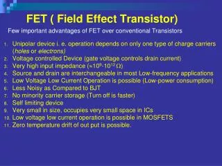
Explore the conductance of the channel, ID-VD characteristics, and the significance of gate voltage in MOSFET operation. Analysis includes output and transfer characteristics as well as mobility models.

E N D
6.1 Transistor Operation 6.2 The Junction FET 6.3 The Metal-Semiconductor FET 6.4 The Metal-Insulator-Semiconductor FET 6.5 The MOS Field-Effect Transistor We analyze the conductance of the channel and find the ID-VD characteristics as a function of gate voltage VG.
Gate voltage permittivity of the insulator Insulator capacitance per unit area Charge in semiconductor The induced charge Qs in the semiconductor is composed of mobile charge Qn and fixed charge in the depletion region Qd. VFB
Mobile charge VFB The induced charge Qs in the semiconductor is composed of mobile charge Qn and fixed charge in the depletion region Qd. With a voltage VD applied, there is a voltage rise Vx from the source to each point x in the channel. (5.60)
Current If we neglect the variation of Qd(x) with bias Vx, the equation can be simplified to The conductance of the differential element dx is At point x we have Width of the channel Surface electron mobility Integrating from source to drain,
Current where determines the conductance and transconductance of the n-channel MOSFET.
Conductance and transconductance The conductance of the channel in the linear region where VG>VT for a channel to exist. As the drain current increased, the voltage across the oxide decreases near the drain, and Qn becomes smaller there. As a result the channel becomes pinched off at the drain end, and the current saturates. The drain current at saturation remains essentially constant for larger values of drain voltage The transconductance in the saturation region
Signs of VD, VG, and VT (output characteristics) The derivations presented before are based on the n-channel device. For the p-channel enhancement transistor the voltage VD, VG, and VT are negative, and current flows from source to drain. n-channel p-channel The output characteristics plot the drain current as a function of the drain bias, with gate bias as a parameter.
6.5.2 transfer characteristics • The transfer characteristics plot the output drain current as a function of the input gate bias, for fixed drain bias.
Linear and saturation region Linear region Saturation region This is not a transfer characteristics plot. However, it is used to illustrate the linear and saturation regions.
Transfer characteristics for linear region • For the transfer characteristics, • ID versus VG should be a straight line. • The intercept of this line on the VG axis is VT(lin.). • The slope gives us kN(lin.). • While the characteristics are approximately linear at low gate bias, at high gate biases the drain current increases sub-linearly. • The transconductance can be obtained by differentiating ID with respect to VG. • The transconductance is zero below VT because there is little drain current. • It goes through a maximum at the point of inflection of the ID-VG curve, and then decreases. • The decrease is due to two factors, (1) degradation of the effective channel mobility as a function of increasing transverse electric field across the gate oxide (6.5.3), and (2) source/drain series resistance (6.5.8).
Transfer characteristics for saturation region • For the transfer characteristics, • We get a linear behavior by plotting not the drain current, but rather the square root of ID, as a function of VG. • The intercept gives us the threshold voltage. • Due to effects such as drain-induced barrier lowering (DIBL) (6.5.10), • for short channel length MOSFETs the VT(sat.) can be lower than VT(lin.), • While the long channel values are similar. • The slope of the transfer characteristics can be used to determine the value of kN(sat.), which can be different from kN(lin.) for short channel devices.
Mobility of carriers in the channel • The mobility of carriers in the channel of a MOSFET is lower than in bulk semiconductors because there are additional scattering mechanisms. • They are scattered by surface roughness, and • by coulombic interaction with fixed charges in the gate oxide. • This mobility degradation increases with the gate bias because a higher gate bias draws the carriers closer to the oxide-silicon interface. • It is very interesting to note that if we plot the effective carrier mobility in the MOSFET as a function of the average transverse electric field in the middle of the inversion layer, we get what is known as a “universal” mobility degradation curve for any MOSFET, which is independent of the technology or device structural parameters such as oxide thickness and channel doping.
Degradation of mobility • The drain current influenced by the degradation of mobility with gate bias is expressed as • is called the mobility degradation parameter. • Because of the additional (VG-VT) term in the denominator, the drain current increases sub-linearly with gate bias for high gate voltages.
Dependence of mobility on drain bias • In addition to the dependence of the channel mobility on gate bias or transverse electric field, there is also a strong dependence on drain bias or the longitudinal electric field. • The maximum longitudinal electric field near the drain end of the channel is approximately given by VD-VD(sat.): voltage drop along the pinch-off region L: length of the pinch-off region • From a two-dimensional solution of the Poisson equation near the drain end, d: gate oxide thickness xj: source/drain junction depth 3: the factor of 3 is due to the ratio of the dielectric constant for Si to that of SiO2
Drain current for short channel devices • For short channel lengths, the carriers travel at the saturation velocity over most of the channel. • The drain current is given by the width times the channel charge per unit area times the saturation velocity. • The saturation drain current does not increase quadratically with (VG-VT), but rather shows a linear dependence. • Not the equal spacing of curves. • Due to the advances in Si device processing, particularly photolithography, MOSFETs used in modern integrated circuits tend to have short channels, and are commonly described by Eq. (6-60) rather than Eq. (6-53). Eq. (6-60) Eq. (6-53)
Considerations of control of threshold voltage • The threshold voltage determines the requirements for turning the MOS transistor on or off. • It is very important to be able to adjust VT in designing the device. • e.g., a 4-V threshold voltage is unacceptable in a circuit driven by a 3-V battery. • Some applications require not only a low value of VT, but also a precisely controlled value to match other devices in the circuit. • All of the terms in Eq. (6-38) can be controlled to some extent. • Фms is determined by choice of the gate conductor material. • F depends on the substrate doping. • Qi can be reduced by proper oxidation methods and by using Si grown in the (100) orientation. • Qd can be adjusted by doping of the substrate. • Ci depends on the thickness and dielectric constant of the insulator. VFB for p-type semiconductor
Control of Gate electrode • In 1960s when first MOSFETs were made, they used Al gates. • However, since Al has a low melting point, it precluded the use of a self-aligned source/drain technology because that required a high temperature source/drain implant anneal after the gate formation. • Hence Al was supplanted by n+ doped LPCVD polysilicon refractory gates, where the Fermi level lines up with the conduction band edge in Si. • A p+ doped polysilicon gate is used for p-channel devices. (why not using n+ doped gate for p-channel ? See 9.3.1) • Refractory metal gates with suitable work functions are also being researched as possible replacements for doped polysilicon. • One attractive candidate is tungsten, whose work function is such that the Fermi level happens to lie near the midgap of Si.
Control of Ci • Since a low value of VT and a high drive current is usually desired, a thin oxide layer is used in the gate region to increase Ci=i/d. • Reduction of d • For practical considerations, the gate oxide thickness is generally 20-100 Å(2-10 nm) in modern devices having submicron gate length. • Increase of i • A SiO2 layer which has some N incorporated in it, leading to the formation of a silicon oxynitride, is often used. Slightly higheri than SiO2, with excellent interface properties. • Other high-k dielectric materials such as Ta2O5, ZrO2 and ferroelectrics (e.g., BaTiO3) are also being investigated as replacements for SiO2. • Generally speaking, we cannot use these high dielectric constant materials directly on the Si substrate. • A very thin (0.5 nm) interfacial SiO2 layer is needed to achieve a low fast interface state density. • A physically thicker layer, d, can be used than for SiO2 and still achieve a certain Ci. • A physically thicker layer implied a wider tunneling barrier with reduced tunneling probability, and reduced leakage current.
Control of Ci in the field Although a low threshold voltage is desirable in the gate region of a transistor, a large value of VT is needed between devices. • We do not want inversion layers to be formed inadvertently between devices. • Generally region between devices is called field. • One way to avoid such parasitic channels is to increase VT in the field by using a very thick oxide. • Typically 0.5 m.
Threshold adjustment by ion implantation • The most valuable tool for controlling threshold voltage is ion implantation. • Since very precise quantities of impurity can be introduced by this method, it is possible to maintain close control of VT. • Reduce VT by boron implantation for p-channel (n substrate) • Boron implantation through the gate oxide of a p-channel device such that the implanted peak occurs just below the Si surface. • The negatively charged boron acceptors serve to reduce the effects of the positive depletion charge Qd. • As a result, VT becomes less negative. • Increase VT by boron implantation for n-channel (p substrate) • As required for an enhancement device.
When boron distribution lies deeper below the surface • If the implantation is performed at higher energy, or into the bare Si instead of through an oxide layer, the impurity distribution lies deeper below the surface. • In such case, the essentially Gaussian impurity concentration profile cannot be approximated by a spike at the Si surface. • Therefore, effects of distributed charge on the Qd term must be considered. • Calculations of the effects on VT in this case are more complicated. • The shift of threshold voltage with implantation dose is often obtained empirically instead.
Effect of implant dose • The implantation dose required for shallow VT adjustment implants is low. • 50-100 keV. • 10 seconds. (convenient for large-scale production) • If the implantation is continued to higher doses, VT can be moved past zero to the depletion-mode condition. • Allowing enhancement- and depletion-mode devices to be incorporated on the same chip. • Normally on: depletion mode (VG to deplete a channel). Channel exist with zero bias. • Normally off: enhancement mode (VG to induce a channel). Channel does not exist without bias.
Implantation for isolation • As mentioned, VT control is important not only in the MOSFETs but also in the isolation or field regions. • In addition to using a thick field oxide, we can do a channel stop implant selectively in the isolation regions under the field oxide. • Channel stop implant is so called because it stops turning on a parasitic channel in the isolation regions. • Generally, a B channel stop implant is used for n-channel devices. • Such an acceptor implant will raise the field thresholds for n-channel MOSFETs made in a p-substrate. • But will decrease the field thresholds for p-MOSFETs made in an n-substrate.
Substrate bias effect • It is possible to apply a voltage between S and B. • With a reverse bias between the substrate and the source (VB negative for an n-channel device), • the depletion region is widened • The threshold gate voltage required to achieve inversion must be increased to accommodate the larger Qd. (6-32) (6-61)
Substrate bias effect on threshold (6-32) (6-61) • If the substrate bias VB is much larger than 2F (typically ~0.6 V), the threshold voltage is dominated by VB. VB will be negative for the n-channel case. • The threshold voltage becomes more positive as the substrate bias is increased. • The effect of this bias becomes more dramatic as the substrate doping is increased, • since VT is also proportional to Na. VB will be positive for the p-channel case. • The threshold voltage becomes more negative with substrate bias.
Body effect • The substrate bias effect (also called the body effect) increases VT for either type of device. • This effect is an asset for n-channel devices. • This effect can be used to raise the threshold voltage of a marginally enhancement device (VT ≈0) to somewhat larger and more manageable value. • The effect can present problems, however. • in MOS integrated circuits for which it is impractical to connect each source region to the substrate. • Possible VT shift due to the body effect must be taken into account in the circuit design.
Subthreshold conduction ? • There is still some drain conduction below threshold, known as subthreshold conduction. • ID depends exponentially on gate bias VG. • VD has little influence once VD exceeds a few kT/q. • Ln ID as a linear function of VG. • The reciprocal of the slope of this line is known as the subthreshold slope, S. • Typical value ~70mV/decade at room temperature for state-of the art MOSFETs. • A change in the input VG of 70 mV will change the output ID by an order of magnitude. • Clearly, the smaller the value of S, the better the transistor is as a switch. • A small value of S means a small change in the input bias can modulate the output current considerably.
Subthreshold slope S • Between the gate and the substrate, we find the gate capacitance, Ci, in series with the parallel combination of the depletion capacitance in the channel, Cd, and the fast interface state capacitance, Cit. • The equation tells us what fraction of the applied gate bias, VG, appears at the Si-SiO2 interface as the surface potential. • Ultimately, it is the surface potential that is responsible for modulating the barrier between source and drain, and therefore the drain current. • Hence, S is a measure of the efficacy of the gate potential in modulating ID. • From equation, S is improved by reducing the gate oxide thickness. • S is higher for heavy channel doping (which increases the depletion capacitance). • S is higher if the silicon-oxide interface has many fast interface states.
Subthreshold conduction under very small gate voltage • For a very small gate voltage, the subthreshold current is reduced to the leakage current of the source/drain junctions. • This determines the off-state leakage current, and therefore the standby power dissipation. • It also underlines the importance of having quality source/drain junctions. • If the VT is too low • It cannot be turned off fully at VG=0. • Unavoidable statistical variations of VT cause drastic variations of the subthreshold leakage current. • If the VT is too high • One sacrifices drive current, which depends on the difference between the power supply voltage and VT. • Historically, VT of MOSFETs has been designed to be ~0.7 V.