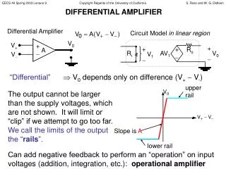
Simple Amplifier Circuit
Simple Amplifier Circuit. Beth Keswani, Les Murphy, and Steve Wilt. What is an amplifier?. An amplifier is an electronic device that enlarges or extends power, current, or voltage. We are using the amplifier for sound. . Amplifiers In Action.

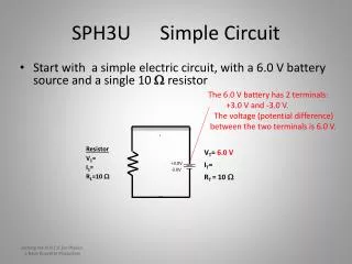
Simple Amplifier Circuit
E N D
Presentation Transcript
Simple Amplifier Circuit Beth Keswani, Les Murphy, and Steve Wilt
What is an amplifier? • An amplifier is an electronic device that enlarges or extends power, current, or voltage. We are using the amplifier for sound.
Amplifiers In Action • Audio amplifiers are used in stereo systems, car systems, and personal radios. Bands also use amplifiers to create a louder sound. I have an amp in me! Whoa! That’s loud!!! This is Les
Capacitors Op amp Resistors Wave generator for voltage input Variable Resistor What Do We Need? • Op Amp- LM386 • Variable Resistor- 102 • Capacitors- 10μF and 250μF • Voltage Input- 1KHz • Low Impedence Resistor- 4Ω, 8Ω, 16Ω, 32Ω
How to Read the Results • The yellow wave is the output. • The blue wave is the input. • We can tell this worked because there is a gain, so it shows that the amplitude was increased. • To calculate the gain, we used channel 1 (yellow wave) peak to peak channel 2 (blue wave) peak to peak.
The Tektronic Results Are In… • This is using a 4Ω resistor. • The gain is 154.
More Fun Graphs… • This is using the 8Ω resistor. • The gain is 205.
Keep The Fun Coming… • This is using the 16Ω resistor. • The gain is 170.
Aw…the fun is almost over • This is using the 32Ω resistor. • The gain is 189.
PSpice and Tektronic Team Up! • These results will show the PSpice results and the Tektronic results compared together. Each PSpice result includes a graph similar to the Tektronic results and also a graph showing the frequency.
Using the 4Ω resistor Percent Error is 54%
Using the 8Ω resistor Percent Error is 2.5%
Using the 16Ω resistor Percent Error is 15%
Using the 32Ω resistor Percent Error is 16%