Download
1 / 24
240 likes | 340 Vues
Steady-State and Dynamic Performance Characterization of a Microturbine. Power System 2002 Impact of Distributed Generation Conference March 13-15, 2002 Clemson, SC Rick Langley EPRI PEAC Corporation Knoxville, TN. Microturbine System Under Test.

E N D
Steady-State and Dynamic Performance Characterization of a Microturbine Power System 2002 Impact of Distributed Generation Conference March 13-15, 2002 Clemson, SC Rick Langley EPRI PEAC Corporation Knoxville, TN
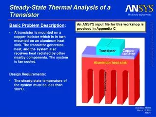
Microturbine SystemUnder Test • Microturbine installed in EPRI PEAC’s Distributed Resource and Power Quality Park (DRPQ Park) in January of 2001 • The system was installed for technology demonstrations and lab testing of DER technologies.
Three-phase Inverter-based DER Grid-Dependent 400-480Vac, 45-65Hz Grid-Independent 150-480Vac, 10-60Hz Automatic “mode-transfer” capability allows the unit to automatically switch from grid-dependent mode to grid-independent mode and back, based on the health of the utility power supply. Distributed Resource Type Microturbine Generator Grid-Dependent Capable Yes Grid-Independent Capable Yes Automatic Mode-Transfer Yes Output kW, kVA – Grid-Dependent 28, 28 Output kW, kVA – Grid-Independent 28, 40 (@ 0.7pf min) Fuel Type / Fuel Pressure Low-pressure Natural Gas / 15 psi Microturbine SystemUnder Test
Microturbine SystemUnder Test • The microturbine does not have a discrete generator or combination generator/feeder protection relay. • The microturbine relies on its own microprocessor-based protection system that is built into the system controls. • The system has a separate voltage monitor relay used to determine if the power grid is suitable for connection (nominal voltage level and unbalance). • The microturbine’s grid-dependent and grid-independent protective functions are user-programmed (undervoltage, overvoltage, over-frequency, and under-frequency).
The microturbine’s grid-dependent protection functions were set according to IEEE P1547-Draft 8. Microturbine Setup Automatic Mode-Transfer Enabled Automatic Restart Enabled Grid-Dependent Protection Function Settings Type Setpoint Time-Delay Undervoltage Level 1 424.0V (88%) 2.0 sec Undervoltage Level 2 240.0V (50.0%) 0.010 sec (not changeable) Overvoltage Level 1 528.0V (110%) 1.0 sec Overvoltage Level 2 576.0V (120%) 0.010 sec (not changeable) Under-frequency 59.3Hz 0.010 sec (not changeable) Over-frequency 60.5Hz 0.010 sec (not changeable) Microturbine SystemUnder Test
Grid-Dependent Tests Characterization of Nominal Voltage Tolerance Thresholds Voltage Unbalance, Overvoltage, & Undervoltage Tests. Characterization of Response to Voltage Variations Voltage Sags, Swells, Capacitor-Switching Transients. Tendency to Island Voltage interruptions and Single-Phasing. Grid-Dependent Tests Characterization of Dynamic Loading Performance Resistive Step Loading Motor Starting Test Categories
Characterization of Nominal Voltage Tolerance Thresholds • Changes in the Local EPS Nominal Voltage • Undervoltage • Overvoltage • Voltage Unbalance
Voltage Unbalance Tests Local EPS voltage unbalance was slowly varied until the microturbine tripped, i.e., ceased to energy the Local EPS. The microturbine tripped at 3% voltage unbalance. Undervoltage Tests Local EPS voltage level was slowly decreased until the microturbine tripped. The microturbine tripped at ~90% of nominal voltage. Overvoltage Tests Local EPS voltage was slowly increased until the microturbine tripped. The microturbine tripped at ~110% of nominal voltage. Characterization of Nominal Voltage Tolerance Thresholds
Characterization of Nominal Voltage Tolerance Thresholds • Significance • The IEEE P1547 standard does not specifically identify these tests. • However, these issues are important because they represent of the potential variability in electric power systems. • DER systems should be designed so that they are compatible with the normal variability of the Local EPS.
Characterization of Response to Voltage Variations • Single-phase, two-phase, and three-phase voltage sags of various magnitudes and durations were applied to the Local EPS.
Characterization of Response to Voltage Variations • Significance • According to IEEE P1547, a DG system should trip offline if the magnitude of the Local EPS voltage falls below 88% for 2 seconds or 50% for 10 cycles. • It also states that the DG shall not reconnect until the Local EPS voltage is within Range B of ANSI C84.1. • The test results show that the microturbine system under test responded in a manner that was consistent with the programming of the microturbine’s grid-dependent protective functions and the criteria defined by the IEEE draft standard.
Tendency to Island • Single- and three-phase voltage interruptions were applied to the Local EPS at several different durations.
Microturbine Setpoint Load Setpoint Interruption Type Response Time 30kW 15kW Single-Phase 42 cycles (0.7 sec) 15kW 15kW Single-Phase 1440 cycles (24.0 sec) 7.5kW 15kW Single-Phase 120 cycles (2.0 sec) 15kW 15kW Three-Phase 1 cycle (0.017 sec) Tendency to Island
Tendency to Island • Significance • Significant variability in detection time to single-phasing conditions based on the microturbine and load setpoints. • Single-phasing detection times were greater than the Voltage Disturbance criteria defined by IEEE P1547 (reference Section 4.2.1) . • IEEE P1547 criteria for voltage <50% of nominal is 0.16 sec. • Three-phase interruption detection time was very fast with little variability in response regardless of the microturbine and load setpoints.
Tendency to Island • Significance • None of the relevant standards (IEEE P1547, IEEE 929, and UL 1741) directly address how three-phase DER systems should react to single-phasing conditions . • There will be many locations where distribution protection equipment, such as fuses, sectionalizers, or reclosers, may open only one phase in a three-phase system. • These test results clearly demonstrate the need for the clarification of the classification of single-phasing in the DER interconnection standards.
Characterization of Dynamic Loading Performance • The objective was to characterize the microturbine system’s grid-independent performance during dynamic loading conditions: • Motor Starting • Resistive Step-Loading
15kW to 30kW Resistive Step Load The temporary voltage drop was less than 5% of nominal. 30kW to 15kW Resistive Step Load The temporary voltage rise was less than 6% of nominal. Characterization of Dynamic Loading Performance
“Line-starting” of a 5-hp (3.73-kW) three-phase induction motor. The voltage on Phase A was reduced to 28% of its nominal value. Phases B and C were affected to a lesser degree at 58% and 81% of nominal, respectively. The system voltage returned to nominal as soon as the motor accelerated to the full speed. Characterization of Dynamic Loading Performance
Characterization of Dynamic Loading Performance • Significance • The ability to operate Distributed Energy Resources in grid-independent modes can significantly increase system reliability. • When grid power is not available, DER systems can be valuable assets to maintain critical facility loads. • However, compatibility between the critical loads and the standby DER can be an issue. • In some cases, alternative-starting methods, such as soft-starters for “line-connected” motors, may be required.
Conclusion • Distributed energy resources hold great promise for improving the efficiency and reliability of the nation’s electric power systems. • However, before the full benefits of DER can be realized, a number of potential barriers to interconnection of DR equipment must be overcome. • In its recent report, “Making Connections,” DOE’s National Renewable Energy Laboratory (NREL) identified a number of technical issues, business practices, and regulatory rules that can increase the cost of and unnecessarily delay or even stop viable projects with potential benefits for both end users and power-delivery companies.
Conclusion • EPRI, the utility industry, and the DOE are responding with initiatives to test and certify DER hardware with research projects aimed at “breaking down the barriers” to interconnection by answering technical questions about DER capabilities for end-users and the electric utility grid through: • Developing engineering guides, software tools, and test protocols, • Conducting field demonstrations and laboratory testing, and • Supporting education, training, and standards development activities for DER. • Testing of this microturbine DER system supports these initiatives.
Conclusion • The microturbine has operated reliably during many grid voltage disturbance tests and demonstrations. • Its built-in protection functions have met most, but not all the response expectations of IEEE P1547 and utility wires companies. • The single-phasing issue is still open. • Analysis of the test results reveals that this system is best suited for grid-connect that do not have interruption-free power requirements and standby power applications . • In grid-independent or standby power applications, load and microturbine compatibility should be reviewed before installation. • Alternative load starting and powering methods may be required. • Testing continues on the microturbine system at the EPRI PEAC laboratory.
Acknowledgements • This research was supported in part by the U.S. Department of Energy, Office of Power Technologies under Contract DE-AC05-00OR22725 with UT-Battelle. • Member’s of EPRI’s Completing the Circuit for their support of this research.