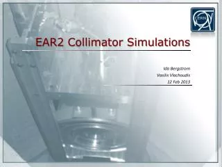
Remote Controlled Measurements for LHC Collimator Alignment: Development and Current Status
This document provides an overview of the development and implementation of a remote-controlled measurement system for the alignment of collimators in the Large Hadron Collider (LHC). Key motivations include managing significant activation of materials due to beam cleaning and ensuring personnel safety through precise alignment control (0.2 mm precision) according to the ALARA principle. The innovative "TIM" Train Inspection Monorail concept integrates various modules for visual inspections and non-contact measurements using digital photogrammetry, with advanced sensors and technology for reliable operation in hazardous environments.

Remote Controlled Measurements for LHC Collimator Alignment: Development and Current Status
E N D
Presentation Transcript
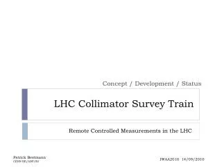
LHC Collimator Survey Train Concept / Development / Status Remote Controlled Measurements in the LHC Patrick Bestmann CERN BE/ABP/SU IWAA2010 14/09/2010
Motivation • Remanent dose rate map between D4 and Q5 after 180 days of continious operation with one month of cooling time
Motivation • Significant activation of material by the beam cleaning process in Point 3 and 7 • High Dose rates for peronnel in Place (4mSv/h) • 500m of Beamline concerned at Point 7 • 26 Quadrupoles and 37 Collimators • Conventionalmeasurements ~90h • Control of the Collimator Alignmentusing a remote controlled system
Task definition • Control of the collimator alignment in vertical and horizontal direction • Relative to the neigbouring quadrupoles • Requested precision 0.2 mm • Respecting the ALARA principle (As Low As Reasonably Achievable)
„TIM“ Train Inspection Monorail • How to bring theequipmentin place? • Train based on themodular TIM concept • Train forvisualinspections • TractionModule • BatteryModule • Sensor Module • Control Module • The trainis controlled either by the user Interface or the measurementprogram
„TIM“ Train Inspection Monorail Tractionunit Sensor unit Controlunit Batteryunit
Concept • Digital closerangephotogrammetry • Fast and non contactmeasurement of theactivatedcollimators • Wireoffsetmeasurementstodetecttrainpositionand link the different aquisitionvolumes. • Reliablestraightreferenceoverlongdistances • Precise model forthewire sag isneeded Collimators Quad Quad
Concept Collimator Quad Quad Targets Wire Sensor Cameras
Concept Targets External lights Wire Reference Pin Inclination sensor
Sensors • AEROEL XLS35-XY laser micrometer as wire measurement system • Open sensor configuration • Large field of view 35mm • Commercial on the market • AICON MoveInspect HR Photogrammetric system • WYLER Zerotronic Inclination Sensors
XLS-35 Micrometer • Optical Laser Micrometer • Measurement of dark/lighttransistions • Relative positionof 2 wirestothereferencepin • 200Hz aquisitionfrequency • Linearityof ±2.5µm • Repeatabilityof ±2µm
Photogrammetric System • Commercial Photogrammetric system AICON MoveInspect HR • 4 AVT Marlin F-201B Cameras in industrial housing • Syncbox • Calibration Panel • MoveInspect HR software • Custom modifications MoveInspectHR
Photogrammetric System • Single shotsynchronisedaquisition • Automatic image measurement andcalculations • We obtain a set of 3D coordinates with identified point groups for collimator andwiresensorsystems • Nosimultaneouscalibration; adjustedintersections
Targets • Retro targets are sensitive to radiation • Use of non retro targets • Production of special aluminium targets • whole body made of black matt aluminium • with light grey aluminium insert
Calculations • 3 different coordiante systems • Left arm with measured wire • Right arm with measured wire • Photogrammetric system with arms and collimator • 7P transformations of the arm systems into the photosystem • Axis alignment to the wire using 3 translations and 2 rotations • Rotation of the y axis (wire axis) using the measured inclination of the two arms
Systems Arm System Camera System
Resultsare 3D coodinatesfor each collimatorandquadrupole in following coordinate system: • Aligned with the inclined wire • Z axis in a vertical plane • Generating LGC++ file • using the x coordinates as horizontal offsets • using the z coordinates as vertical distances (reduced by the slope and the wire sag) • Online LGC++ calculation and comparison with theoretical values
Operation • Autonomoussystem after thestartupprocedure • Startup; Calibration; Sequencedefinition • ControlledbytheLabView Software • Sequencerrunning on thetrain • Remote Panel informingtheoperator
Status • Sensorsystems are running • All Subroutines are running • Tunnelinstallation completed • Finalising Software • Finalising Hardware configuration • Tests.....