Download
1 / 27
280 likes | 430 Vues
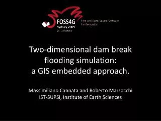
Two-dimensional dam break flooding simulation: a GIS embedded approach. Massimiliano Cannata and Roberto Marzocchi IST-SUPSI, Institute of Earth Sciences. Risk assessment. GISs are invaluable in risk assessment due to their capability in solving the location issue Where happens ?

E N D
Two-dimensional dam break flooding simulation: a GIS embedded approach. MassimilianoCannata and Roberto Marzocchi IST-SUPSI, Institute of Earth Sciences
Riskassessment • GISs are invaluable in risk assessment due to their capability in solving the location issue • Wherehappens? • Whataretheextension? • Who and whatisthere? WHILE • Models solve equations to simulate the phenomena (area and intensity of events)
GIS-Modelintegration GIS MODEL GIS MODEL CONVERSION Independent Loosely coupled INTERFACE GIS MODEL GIS MODEL GIS MODEL Embedded Tightly coupled
Why another model? • To take into account the location, models implement their own “spatial” functions and libraries, but these already exist within GISs at an highly specialized level (as a result of decades of development) CURRENTLY • GISs lack of extensive environmental modelling capabilities and therefore risk assessment studies imply the usage of different software, systems and environments SO • We decided to Improve GIS simulation capability developing GIS EMBEDDED MODELS
Open or Proprietary software? • Total cost is NOT = $0 • Many applications are not as polished as the proprietary counterparts • Compatibility with proprietary software and formats can be an issue • Separate packages require multiple installation and maintenance • Documentation is sometime poor • Linkage with Proprietary software (can be hard) • User Interfaces are often the last development • Software cost = $0 • Source code is available and modifiable • User and development communities flourish • Development cycles are VERY fast • Platform support (i.e. UNIX, Linux, Windows, Mac OS) • Speed and efficiency • Numerous data format support • Standards for interoperability (OGC specs)
Open or Proprietary software? Total cost is NOT = $0 Many applications are not as polished as the proprietary counterparts Compatibility with proprietary software and formats can be an issue Separate packages require multiple installation and maintainance Documentation is sometime poor Linkage with Proprietary software (can be hard) User Interfaces are often the last development Software cost = $0 Source code is available and modifiable User and development communities flourish Development cycles are VERY fast Platform support (i.e. UNIX, Linux, Windows, Mac OS) Speed and efficiency Numerous data format support Standards for interoperability (OGC specs) SMOTH INTERFACES C sourcecode GRASS GIS is a maturesolution EXCELLENT FORMATS SUPPORT ROBUST LIBRARY NATIVE PAKAGES GOOD DOCUMENTATION
Flash floods due to dam failure • Most of the dams were built in the 40s – 70s • In many countries maintenance founds are poor • High development in downstream valleys in the last decades Need for updated risk assessment and emergency plans Vajont, 9 October 1963
Example of dam failure risk • Romania, Sacele Dam: Landslide threatening water outlet tower and likely generating impact wave causing overtopping and consequent dam erosion and failure
Approach: problemformulation Mathematical model that solves the conservative form of the 2D Shallow Water Equations (SWE) using a Finite Volume Method (FVM) and produce maximum intensity maps that can be directly used for risk assessment and emergency plans development.
Shallow Water Equations: assumptions Good approximation to fluid motion equations when fluid density is homogenous and depth is small in comparison to characteristic horizontal distances: • component of velocities along the vertical direction is negligible if compared to the horizontal ones • the pressure distribution over the flow depth is nearly hydrostatic Free surface The 3D Navier – Stokes governing fluid dynamic equations are integrated on the depth and conduct to a 2D formulation of the problem h Vh Vz
Shallow Water Equations: formulation • U = vector of conserved variables • F = x-direction flux vector • G = y-direction flux vector • S = source vector • h = water depth [m], • u = x-direction flow velocity [m/s], • v =y-directions flow velocity [m/s], • g = gravitational acceleration [m/s2], • Z = water level expressed in orthometric height [m a.s.l.] • n = Manning’s roughness coefficient [s/m1/3]
Shallow Water Equations: solution applying the Upwind Conservative Scheme by Ying et al. [2004] we get the solution With the one-sided upwind method we solves explicitlythis equation in two separate steps: the continuity equation is evaluated deriving the water depth at time t+1, these values are used to solve the momentum equations that provide the flow velocities at time t+1
r.damflood • Input options • elevation raster map (accounting for reservoir's bathymetry and dam elevation); • lake water depth raster map (easily obtained with r.lake GRASS GIS module); • dam breach width raster map (decreased dam height due to failure); • manning’s roughness coefficient raster map; • simulation time length. • simulation timestep • Output options • time-lag for outputs generation; • additional instants for output map generation; • prefix for water depth output tseries raster maps; • prefix for water velocity output tseries raster maps; • maximum water depth and relative time output raster map; • maximum water velocity and relative time output raster map; • maximum intensity output and relative time raster map. Intensity = max(h,v·h) [>2,2-0.5,<0.5] (time series raster maps are coded as prefix + _ + elapsed seconds: e.g. mydepth_125)
Model verification (synthetic case 1) • 2D Partial instantaneous dam-break: to evaluate the capability in modeling different severe hydrodynamic difficulties upstream water depth hu =10 m downstreamwaterdepthhd = 0 m timestep = 0.01 s t = 6 s upstream water depth hu =10 m downstreamwaterdepthhd = 0.1 m timestep = 0.01 s t = 6 s upstream water depth hu =10 m downstreamwaterdepthhd = 5 m timestep = 0.01 s t = 6 s
Model verification (synthetic case 2) • 2D breaking of a circular dam in a rectangular domain: to evaluate the capability in modeling symmetric dam-break flow upstream water depth hu =10 m downstreamwaterdepthhd = 0 m timestep = 0.005 s t = 0.69 s upstream water depth hu =10 m downstreamwaterdepthhd = 1 m timestep = 0.005 s t = 0.69 s upstream water depth hu =10 m downstreamwaterdepthhd = 5 m timestep = 0.005 s t = 0.69 s
Model verification (synthetic case 2) Model behavior at two different grid resolution
Model verification (synthetic case 2) • Small perturbations in axis direction
Model validation • Application to an existing Swiss dam: Verzasca The dam, that is one of the highest dam in the world (220 m), forms the Vogorno Lake, a wide artificial reservoir with a maximum water level of 469 m a.s.l., a volume of 105 Mio mP3P, a surface of 1,68 Mio mP2P and a length of 5.5 km [http://www.swissdams.chUTH].
Model validation: simulationrun • computational domain: • E-W size: 20,025 m • N-S size: 20,000 m • Resolution: 25m • Total cells number: 640,000 • simulation timestep: 0.01s • simulationlength: 3600 s • computational running time: 16 h 39’ 53’’ (on a 1.7 GiB memory, 2 Intel® Core™ 2 Duo CPU E 4500 computer)
Model validation: waterdepth • Maximum waterdepthmap(h[m])
Model validation: watervelocity • Maximum watervelocitymap(V [m/s])
Model validation: intensity • Maximum intensitymap(F [m2/s])
Model validation: floodextension hazard zone covered by simulation residual hazard zone covered by simulation residual hazard zone not covered by simulation simulation on no hazard zone
Model validation: timing 15 s 30 s 45 s Comparison between existent front wave vector map and obtained raster map
Future works Adaptive timestep length: like other explicit numerical schemes, the stability of proposed solution is driven by the Courant-Friedrichs-Lewy condition: practically there is a relationship between grid resolution, velocities, water depth and timestep: at equal resolution for higher velocities smaller timestep are required. We will develop an dynamic adaptive procedure setting timestep length to guarantee stability and minimize computational times. Overtopping: the model currently account for total or partial dam break, we are considering to extend the model to account for overtopping events too. Comparison with other models: compare simulation results, input requirements and computational times
Conclusions • We have developed a GIS embedded module for dam break modeling that is suitable for risk assessment. • We have validated this model proving the correctness of the simulation qualitatively and quantitatively • We have shown how environmental models can be efficiently integrated in FOSS4G
Thank you for your attention Visit http://istgeo.ist.supsi.ch/site/projects/dambreak for more information