Angle Modulation
Angle Modulation. Angle modulation includes both frequency and phase modulation. FM is used for: radio broadcasting, sound signal in TV, two-way fixed and mobile radio systems, cellular telephone systems, and satellite communications.

Angle Modulation
E N D
Presentation Transcript
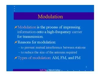
Angle Modulation • Angle modulation includes both frequency and phase modulation. • FM is used for: radio broadcasting, sound signal in TV, two-way fixed and mobile radio systems, cellular telephone systems, and satellite communications. • PM is used extensively in data communications and for indirect FM.
Comparison of FM or PM with AM Advantages over AM: • better SNR, and more resistant to noise • efficient - class C amplifier can be used, and less power is required to angle modulate • capture effect reduces mutual interference Disadvantages: • much wider bandwidth is required • slightly more complex circuitry is needed
PLL FM Detector • PLL and quadrature detectors are commonly found in modern FM receivers. Phase Detector Demodulated output FM IF Signal f LPF VCO
Quadrature Detector • Both the quadrature and the PLL detector are conveniently found as IC packages.
Radio-Wave Propagation • Radio waves, infrared, visible light, ultraviolet, X rays, and gamma rays are all different forms of electromagnetic radiation. • The waves propagate as transverse electromagnetic waves (TEM) - i.e. the electric field, the magnetic field, and the direction of travel of the waves are all mutually perpendicular.
Transverse Electromagnetic Waves z Direction of Propagation y Magnetic Field Electric Field x
Speed & Wavelength of em Waves • The speed of propagation () and the wavelength (l) of an electromagnetic wave are given, respectively, by: where c = 3x10⁸ m/s, r = medium’s relative permittivity or dielectric constant, and f = frequency of wave in Hz.
Reflection Radio waves behave like light waves: • They reflect from a surface where the angle of incidence, qi = the angle of reflection, qr . To minimize reflective losses, the surface should be an ideal conductor and smooth. Reflected Ray Incident Ray Normal qi qr Conductor
Refraction • Radio waves will bend or refract when they go from one medium with refractive index, n1 to another with refractive index, n2. The angles involved are given by : q1 where r = relative permittivity of medium q2 n1<n2
Diffraction • Diffraction is the phenomenon which results in radio waves that normally travel in a straight line to bend around an obstacle. Direction of wave propagation Obstacle
Ground-Wave Propagation • At frequencies up to about 2 MHz, the most important method of propagation is by ground waves which are vertically polarized. They follow the curvature of the earth to propagate far beyond the horizon. Relatively high power is required. Direction of wave travel Increasing Tilt Earth
Ionospheric Propagation • HF radio waves are returned from the F-layer of the ionosphere by a form of refraction. • The highest frequency that is returned to earth in the vertical direction is called the critical frequency, fc. • The highest frequency that returns to earth over a given path is called the maximum usable frequency (MUF). Because of the general instability of the ionosphere, the optimum working frequency (OWF) = 0.85 MUF, is used instead.
Sky-Wave Propagation • From geometry (assuming flat earth): d = 2hv tan qi • From theory (secant law): MUF = fc sec qi F-Layer qi hv Earth d
Sky-wave Propagation: Pros & Cons • Sky-wave propagation allows communication over great distances with simple equipment and reasonable power levels : 100 W to a few kW. • However, HF communication via the ionosphere is noisy and uncertain. It is also prone to phase shifting and frequency-selective fading. For instance, the phase shift and signal attenuation may be different for the upper and lower sidebands of the same signal. Data transmission is restricted to very low rates.
Space-Wave Propagation • Most terrestrial communications in the VHF or higher frequency range use direct, line-of-sight, or tropospheric radio waves. The approximate maximum distance of communication is given by: where d = max. distance in km hT = height of the TX antenna in m hR = height of the RX antenna in m
Space-Wave Propagation (cont’d) • The radio horizon is greater than the optical horizon by about one third due to refraction of the atmosphere. • Reflections from a relatively smooth surface, such as a body of water, could result in partial cancellation of the direct signal - a phenomenonknown as fading. Also, large objects, such as buildings and hills, could cause multipath distortion from many reflections.
Optical Fibre Communications • Advantages over metallic/coaxial cable: • much wider bandwidth and practically interference-free • lower loss and light weight • more resistive to environmental effects • safer and easier to install • almost impossible to tap into a fibre cable • potentially lower in cost over the long term • Disadvantages: • higher initial cost in installation & more expensive to repair/maintain
Optical Fibre Link Transmitter Input Signal Coder or Converter Light Source Source-to-fibre Interface Fibre-optic Cable Output Light Detector Fibre-to-light Interface Amplifier/Shaper Decoder Receiver
Types Of Optical Fibre Light ray n1 core n2 cladding Single-mode step-index fibre no air n1 core n2 cladding Multimode step-index fibre no air Variable n Multimode graded-index fibre Index porfile