Angle Modulation
Angle Modulation. "All of RF is Truly FM" SIGA2800 Basic SIGINT Technology. Objectives. Identify which modulations are also known as angle modulations.

Angle Modulation
E N D
Presentation Transcript
Angle Modulation "All of RF is Truly FM" SIGA2800 Basic SIGINT Technology
Objectives • Identify which modulations are also known as angle modulations. • Given a maximum modulating frequency and either a frequency of deviation or deviation ratio of a frequency modulated signal, determine signal bandwidth as given by Carson's rule.
Objectives • Given a bandwidth and either a maximum frequency deviation or deviation ratio, compute the maximum modulating frequency that will comply with Carson's rule.
Objectives • Given a carrier being frequency modulated by a sine wave at a fixed deviation ratio, compute: • Average signal power • Bandwidth in accordance with Carson's rule. • Signal power present at the carrier frequency, any frequency harmonic, and at a frequency equal to the frequency deviation.
Objectives • For angle modulated signals, identify what factors drive overall power in the signal. • State what factors affect the bandwidth of signals modulated using angle modulation.
Sinusoids Sinusoid waveform Cosinusoid waveform A sinusoid, meaning a sine wave -or- a cosine wave, is the basic building block of all signals.
Sinewave Characteristics Amplitude Amplitude Phase Period Time A sinusoid has three properties . These are its amplitude, period (or frequency), and phase.
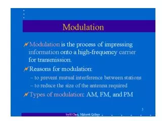
Types of Modulation Amplitude Modulation Phase Modulation With very few exceptions, phase modulation is used for digital information. Frequency Modulation
Types of Modulation Carrier Variations • Amplitude • Frequency • Phase Types of Information • Analog • Digital These two constitute angle modulation. (Objective #1)
Modulator Modulation Process Modulating Signal Information / Baseband Modulated Signal The modulation general process is the same regardless of the how the carrier is modulated. For our purposes, modulation means the variation of a carrier wave in order to transfer information.
What is Angle Modulation? Phase Frequency Amplitude Angle modulation is a variation of one of these two parameters.
Understanding Phase vs. Frequency To understand the difference between phase and frequency, a signal can be thought of using a phasor diagram. The distance from the center is the signal's amplitude. The angle from the positive horizontal axis is the phase. V phase
Understanding Phase vs. Frequency (change phase)/(change time) The change in the phase over time (the phase velocity) is the signal's frequency.
Signals vs NASCAR F In signals, we track the signal by its phase. This is its position on the phasor diagram. In NASCAR, we track each car by its position on the track.
Signals vs NASCAR In signals, we track the signal's velocity by its frequency. This is how fast it goes around the phasor diagram. In NASCAR, we track a car's velocity by how fast it goes around the track.
Understanding Angle Modulation Frequency Modulation Phase Modulation Angle modulation, either PM or FM, varies the frequency or phase of the carrier wave. Because of the practicalities of implementation, FM is predominant; analog PM is only used in rare cases. Vary one of these parameters
Understanding Angle Modulation Frequency Modulation V Phase Modulation V In either analog FM or PM, the amplitude remains constant. This remains constant!
Understanding Angle Modulation Frequency Modulation Envelope V The envelope, meaning the difference between the maximum and minimum of the carrier, is constant in an FM signal. That's why FM is called a constant envelope signal. The power of an FM signal is shown at right. It does not depend upon the modulating signal or the amount of deviation (Objectives #4a, 5).
Calculating Total Power The total power of an FM signal is simply V2. Therefore, the total power of an FM signal is the power of the carrier. Period. This is regardless of the information or the deviation ratio (Objectives #4a, 5).
Varying the Frequency Information Signal VCO Frequency Modulation The voltage-controlled oscillator (VCO) is a device whose output frequency changes with the amplitude of the modulating signal. The amount of change, called its deviation constant, is dependent upon its design.
Understanding Terms Center Frequency An FM signal has its energy spread over an infinite number of spectral components. It's center frequency is the average center of the energy.
Understanding Terms Deviation The deviation is the maximum frequency change from the center frequency.
Understanding Terms Excursion The excursion is the difference between the maximum and minimum frequency changes. This is also called the maximum deviation or total deviation.
Amplitude vs Angle Modulation Amplitude Modulation Angle Modulation
Calculating FM Bandwidth The Fourier transform for an FM signal modulated by a real signal would be extremely difficult. Instead, engineers use the special case of an FM signal modulated by sinusoid, which boils down to: This integral cannot be solved in closed form. In order to figure out actual numerical answers, we use Bessel functions, specifically Bessel functions of the first kind of order n and argument b.
Calculating FM Bandwidth Angle Modulation For PM For FM
Calculating FM Bandwidth Angle Modulation The beta value, called the modulation index, is the ratio of the deviation of the modulator, fd, multiplied by the amplitude of the modulating signal and divided by the modulating frequency, fm(Objectives 2, 3, 4b, 6).
Understanding FM Bandwidth b=0.5 b=1 b=5 b=10
Calculating FM Bandwidth Angle Modulation The designator when looking at real signals is the deviation ratio, D, which is the product of the modulator deviation, fd, multiplied by the amplitude of the modulating signal, V, divided by the maximum frequency of the modulating signal, W (Objectives 2, 3, 4b, 6).
Carson's Rule Carson's Rule, named after an engineer who did not think that FM would provide any improvement over AM, provides a rough calculation of the bandwidth of an FM signal based upon its design parameters and the parameters of the modulating signal (Objectives 2, 3, 4b, 6).
FM Spectrum The spectrogram of an FM signal shows how the spectrum varies with time. Note how it is asymmetric. This is the spectrum of an AM signal modulated with the same information as above. But it has a symmetric spectrum.
FM Signal This shows an FM signal. Note the constant envelope (amplitude).
FM Signal This is a constellation diagram of an FM signal. Note how it has a constant amplitude (distance from the center).
Why FM and not PM? For practical implementation reasons, analog FM is easier to generate than analog PM, and FM provides better performance in most common environments. However, analog PM has been (and continues to be) used for a few, isolated systems. • Broadcast analog television chrominance (color) • Apollo spacecraft communications • AM stereo
Calculating FM Bandwidth b Value Spectral Line #