Chapter 4. Angle Modulation
Chapter 4. Angle Modulation. Essentials of Communication Systems Engineering John G. Proakis and Masoud Salehi. Angle Modulation. In Chapter 3 We considered amplitude modulation of the carrier as a means for transmitting the message signal

Chapter 4. Angle Modulation
E N D
Presentation Transcript
Chapter 4. Angle Modulation Essentials of Communication Systems Engineering John G. Proakis and Masoud Salehi
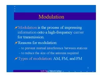
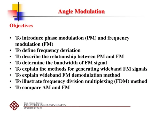
Angle Modulation • In Chapter 3 • We considered amplitude modulation of the carrier as a means for transmitting the message signal • Amplitude-modulation methods are also called linear modulation methods, although conventional AM is not linear in the strict sense • Another class of modulation methods include frequency and phase modulation which are described in this chapter • In frequency-modulation (FM) systems, the frequency of the carrier fcis changed by the message signal • In phase modulation (PM) systems, the phase of the carrier is changed according to the variations in the message signal • Frequency and phase modulation are nonlinear, and often they are jointly called angle-modulation methods Oh-Jin Kwon, EE dept., Sejong Univ., Seoul, Korea: http://dasan.sejong.ac.kr/~ojkwon/
4.1 REPRESENTATION OF FM AND PM SIGNALS • An angle-modulated signal • where fcdenotes the carrier frequency and (t)denotes a time-varying phase • The instantaneous frequency of this signal • If m(t)is the message signal, then in a PM system, the phase is proportional to the message, • In an FM system, the instantaneous frequency deviation from the carrier frequency is proportional with the message signal • where kpand kfare phase and frequency deviation constants Oh-Jin Kwon, EE dept., Sejong Univ., Seoul, Korea: http://dasan.sejong.ac.kr/~ojkwon/
REPRESENTATION OF FM AND PM SIGNALS • From the preceding relationships, we have • First, note that if we phase modulate the carrier with the integral of a message, it is equivalent to the frequency modulation of the carrier with the original message • On the other hand, this relation can be expressed as • which shows that if we frequency modulate the carrier with the derivative of a message, the result is equivalent to the phase modulation of the carrier with the message itself Figure 4.1 A comparison of frequency and phase modulators Oh-Jin Kwon, EE dept., Sejong Univ., Seoul, Korea: http://dasan.sejong.ac.kr/~ojkwon/
REPRESENTATION OF FM AND PM SIGNALS • Figure 4.2 illustrates a square-wave signal and its integral, a sawtooth signal, and their corresponding FM and PM signals Figure 4.2 Frequency and phase modulation of square and sawtooth waves. Oh-Jin Kwon, EE dept., Sejong Univ., Seoul, Korea: http://dasan.sejong.ac.kr/~ojkwon/
REPRESENTATION OF FM AND PM SIGNALS • The demodulation of an FM signal involves finding the instantaneous frequency of the modulated signal and then subtracting the carrier frequency from it • In the demodulation of PM, the demodulation process is done by finding the phase of the signal and then recovering m(t) • The maximum phase deviation in a PM system • The maximum frequency deviation in an FM system • The modulation index for a general nonsinusoidal signal m(t) is defined as • where W denotes the bandwidth of the message signal m(t) • In terms of the maximum phase and frequency deviation and Oh-Jin Kwon, EE dept., Sejong Univ., Seoul, Korea: http://dasan.sejong.ac.kr/~ojkwon/
Narrowband Angle Modulation • Consider an angle modulation system in which the deviation constants kpand kfand the message signal m(t) are such that for all t, we have (t)<<1 • where we have used the approximations cos(t)1 and sin(t)(t) for (t) << 1 • Equation (4.1.19) shows that in this case, the modulated signal is very similar to a conventional-AM signal given in Equation (3.2.5) • The only difference is that the message signal m(t) is modulated on a sine carrier rather than a cosine carrier • The bandwidth of this signal is similar to the bandwidth of a conventional AM signal, which is twice the bandwidth of the message signal • Of course, this bandwidth is only an approximation of the real bandwidth of the FM signal Oh-Jin Kwon, EE dept., Sejong Univ., Seoul, Korea: http://dasan.sejong.ac.kr/~ojkwon/
Narrowband Angle Modulation • A phasor diagram for this signal and the comparable conventional-AM signal are given in Figure 4.3 • Compared to conventional AM, the narrowband angle-modulation scheme has far less amplitude variations • The angle-modulation system has constant amplitude • There should be no amplitude variations in the phasor-diagram representation of the system • These slight variations are due to the first-order approximation that we have used for the expansions of sin((t)) and cos((t)) • The narrowband angle-modulation method does not provide better noise immunity than a conventional AM system • Therefore, narrowband angle-modulation is seldom used in practice for communication purposes • However, these systems can be used as an intermediate stage for the generation of wideband angle-modulated signals, as we will discuss in Section 4.3 Figure 4.3 Phasor diagram for the conventional AM and narrowband angle modulation. Oh-Jin Kwon, EE dept., Sejong Univ., Seoul, Korea: http://dasan.sejong.ac.kr/~ojkwon/
4.2 SPECTRAL CHARACTERISTICS OF ANGLE-MODULATED SIGNALS • Due to the inherent nonlinearity of angle modulation systems, the precise characterization of their spectral properties, even for simple message signals, is mathematically intractable. • Therefore, the derivation of the spectral characteristics of these signals usually involves the study of simple modulating signals and certain approximations. • Then the results are generalized to the more complicated messages. • We will study the spectral characteristics of an angle-modulated signal when the modulating signal is a sinusoidal signal. Oh-Jin Kwon, EE dept., Sejong Univ., Seoul, Korea: http://dasan.sejong.ac.kr/~ojkwon/
4.2.1 Angle Modulation by a Sinusoidal Signal • Consider the case where the message signal is a sinusoidal signal (to be more precise, sine in PM and cosine in FM). • is the modulation index that can be either por f • Using Euler's relation, the modulated signal • Since sin2fmt is periodic with period Tm= 1/fm, the same is true for the complex exponential signal • Therefore, it can be expanded in a Fourier-series representation • The Fourier-series coefficients are obtained from the integral • This latter expression is a well-known integral called the Bessel function of the first kind of order n and is denoted by Jn(). Oh-Jin Kwon, EE dept., Sejong Univ., Seoul, Korea: http://dasan.sejong.ac.kr/~ojkwon/
Angle Modulation by a Sinusoidal Signal • Therefore, we have the Fourier series for the complex exponential as • By substituting Equation (4.2.4) in to Equation (4.2.2), we obtain • The preceding relation shows that, even in this very simple case where the modulating signal is a sinusoid of frequency fm, the angle-modulated signal contains all frequencies of the form fc+nfmfor n = 0, 1, 2, . . . . • Therefore, the actual bandwidth of the modulated signal is infinite. • However, the amplitude of the sinusoidal components of frequencies fcnfmfor large n is very small • Hence, we can define a finite effective bandwidth for the modulated signal Oh-Jin Kwon, EE dept., Sejong Univ., Seoul, Korea: http://dasan.sejong.ac.kr/~ojkwon/
Angle Modulation by a Sinusoidal Signal • For small , we can use the approximation • For a small modulation index , only the sidebands corresponding to n = 0, 1 are important • Also, we can easily verify the following symmetry properties of the Bessel function: • Plots of Jn() for various values of n are given in Figure 4.4. • The values of the Bessel function are given in Table 4.1. Oh-Jin Kwon, EE dept., Sejong Univ., Seoul, Korea: http://dasan.sejong.ac.kr/~ojkwon/
Angle Modulation by a Sinusoidal Signal • Plots of Jn() for various values of n are given in Figure 4.4 Figure 4.4 Bessel functions for various values of n Oh-Jin Kwon, EE dept., Sejong Univ., Seoul, Korea: http://dasan.sejong.ac.kr/~ojkwon/
Angle Modulation by a Sinusoidal Signal • The values of the Bessel function are given in Table 4.1. Oh-Jin Kwon, EE dept., Sejong Univ., Seoul, Korea: http://dasan.sejong.ac.kr/~ojkwon/
Angle Modulation by a Sinusoidal Signal • In general, the effective bandwidth of an angle-modulated signal, which contains at least 98% of the signal power, is given by the relation • where is the modulation index and fm is the frequency of the sinusoidal message signal • It is instructive to study the effect of the amplitude and frequency of the sinusoidal message signal on the bandwidth and the number of harmonics in the modulated signal. • Let the message signal be given by • Using Equations (4.2.14), (4.1.12), the bandwidth of the lated signal is given by Oh-Jin Kwon, EE dept., Sejong Univ., Seoul, Korea: http://dasan.sejong.ac.kr/~ojkwon/
Angle Modulation by a Sinusoidal Signal • The preceding relation shows that increasing a, the amplitude of the modulating signal, in PM and FM has almost the same effect on increasing the bandwidth Bc. • On the other hand, increasing fm, the frequency of the message signal, has a more profound effect in increasing the bandwidth of a PM signal as compared to an FM signal • In both PM and FM, the bandwidth Bcincreases by increasing fm; but in PM, this increase is a proportional increase, and in FM, this is only an additive increase which usually (for large ) is not substantial • Now if we look at the number of harmonics in the bandwidth (including the carrier) and denote it by Mc, we have Oh-Jin Kwon, EE dept., Sejong Univ., Seoul, Korea: http://dasan.sejong.ac.kr/~ojkwon/
4.2.2 Angle Modulation by an Arbitrary Message Signal • The spectral characteristics of an angle-modulated signal for a general message signal m(t)is quite involved due to the nonlinear nature of the modulation process. • However, there exists an approximate relation for the effective bandwidth of the modulated signal. • This is known as Carson's rule and is given by • where is the modulation index defined as • and W is the bandwidth of the message signal m(t) • Since wideband FM has a with a value that is usually around 5 or more, the bandwidth of an angle-modulated signal is much greater than the bandwidth of various amplitude-modulation schemes. • This bandwidth is either W (in SSB) or 2W (in DSB or conventional AM). Oh-Jin Kwon, EE dept., Sejong Univ., Seoul, Korea: http://dasan.sejong.ac.kr/~ojkwon/
4.3 IMPLEMENTATION OF ANGLE MODULATORS AND DEMODULATORS • Any modulation and demodulation process involves the generation of new frequencies that were not present in the input signal. • This is true for both amplitude and angle-modulation systems. • Consider a modulator system with the message signal m(t) as the input and with the modulated signal u(t)as the output • This system has frequencies in its output that were not present in the input. • Therefore, a modulator (and demodulator) cannot be modeled as a linear time-invariant system • Because a linear time-invariant system cannot produce any frequency components in the output that are not present in the input signal. Oh-Jin Kwon, EE dept., Sejong Univ., Seoul, Korea: http://dasan.sejong.ac.kr/~ojkwon/
Angle Modulators • Angle modulators are generally time-varying and nonlinear systems. • One method for directly generating an FM signal is to design an oscillator whose frequency changes with the input voltage. • When the input voltage is zero, the oscillator generates a sinusoid with frequency fc • When the input voltage changes, this frequency changes accordingly. • There are two approaches to designing such an oscillator, usually called a VCO or voltage-controlled oscillator. • One approach is to use a varactor diode. • A varactor diode is a capacitor whose capacitance changes with the applied voltage. • Therefore, if this capacitor is used in the tuned circuit of the oscillator and the message signal is applied to it, the frequency of the tuned circuit and the oscillator will change in accordance with the message signal. Oh-Jin Kwon, EE dept., Sejong Univ., Seoul, Korea: http://dasan.sejong.ac.kr/~ojkwon/
Angle Modulators • A second approach for generating an FM signal is to use a reactance tube. • In the reactance-tube implementation, an inductor whose inductance varies with the applied voltage is employed • The analysis is very similar to the analysis presented for the varactor diode. • Although we described these methods for the generation of FM signals, basically the same methods can be applied for the generation of PM signals (see Figure 4.1), due to the close relation between FM and PM signals. Oh-Jin Kwon, EE dept., Sejong Univ., Seoul, Korea: http://dasan.sejong.ac.kr/~ojkwon/
Angle Modulators • Generation of narrowband FM and PM signals. • Due to the similarity of conventional AM signals, the generation of narrowband angle-modulated signals is straightforward. • In fact, any modulator for conventional AM generation can be easily modified to generate a narrowband angle-modulated signal. • Figure 4.8 shows the block diagram of a narrowband angle modulator. Figure 4.8 Generation of a narrowband angle-modulated signal. Oh-Jin Kwon, EE dept., Sejong Univ., Seoul, Korea: http://dasan.sejong.ac.kr/~ojkwon/
Angle Modulators • FM demodulators are implemented by generating an AM signal • Its amplitude is proportional to the instantaneous frequency of the FM signal, and then using an AM demodulator to recover the message signal. • To implement the first step, i.e., to transform the FM signal into an AM signal, it is enough to pass the FM signal through an LTI system, whose frequency response is approximately a straight line in the frequency band of the FM signal. • If the frequency response of such a system is given by • And if the input to the system is • Then the output will be the signal • The next step is to demodulate this signal to obtain Ac(Vo+kkfm(t)), from which the message m(t) can be recovered. • Figure 4.10 shows a block diagram of these two steps. Figure 4.10 A general FM demodulator. Oh-Jin Kwon, EE dept., Sejong Univ., Seoul, Korea: http://dasan.sejong.ac.kr/~ojkwon/
Angle Modulators • Many circuits can be used to implement the first stage of an FM demodulator, i.e., FM to AM conversion. • One such candidate is a simple differentiator with • Example circuit: Oh-Jin Kwon, EE dept., Sejong Univ., Seoul, Korea: http://dasan.sejong.ac.kr/~ojkwon/
Angle Modulators • 연습문제 1, 2 Oh-Jin Kwon, EE dept., Sejong Univ., Seoul, Korea: http://dasan.sejong.ac.kr/~ojkwon/
Recommended Problems • Textbook Problems from p202 • 4.1, 4.4, 4.7, 4.10, 4.12, 4.17, 4.18, 4.19 • 강의용 홈페이지에 게시된 기출 중간고사 및 기말고사 문제 중 Angle Modulation에 관련된 문제들 Oh-Jin Kwon, EE dept., Sejong Univ., Seoul, Korea: http://dasan.sejong.ac.kr/~ojkwon/