Chapter 4. Angle Modulation
Chapter 4. Angle Modulation. 4.7 Generation of FM Waves. Direct Method A sinusoidal oscillator, with one of the reactive elements in the tank circuit of the oscillator being directly controllable by the message signal


Chapter 4. Angle Modulation
E N D
Presentation Transcript
4.7 Generation of FM Waves • Direct Method • A sinusoidal oscillator, with one of the reactive elements in the tank circuit of the oscillator being directly controllable by the message signal • The tendency for the carrier frequency to drift, which is usually unacceptable for commercial radio applications. • To overcome this limitation, frequency stabilization of the FM generator is required, which is realized through the use of feed-back around the oscillator • Indirect Method : Armstrong Modulator • The message signal is first used to produce a narrow-band FM, which is followed by frequency multiplication to increase the frequency deviation to the desired level. • Armstrong wide-band frequency modulator • The carrier-frequency stability problem is alleviated by using a highly stable oscillator
A Frequency multiplier • A memoryless nonlinear device • The input-output relation of such a device is • A new FM wave is
4.8 Demodulation of FM Signals • Frequency Discriminator • The FM signal is • We can motivate the formulation of a receiver for doing this recovery by nothing that if we take the derivative of Eq. (4.44) with respect to time • A typical transfer characteristic that satisfies this requirement is
The slope circuit • The circuit is also not required to have zero response outside the transmission bandwidth • The complex envelope of the FM signal s(t) is
Multiplication of the Fourier transform by j2πf is equivalent to differentiating the inverse Fourier transform • Application of the linearity property to the nonzero part of yields the actual response of the slope circuit due to the FM wave s(t) is given by
The envelope detector • Under ideal conditions, the output of the envelope detector is • The overall output that is bias-free
Phase-Locked Loop • A feedback system whose operation is closely linked to frequency modulation • Three major components • Voltage-controlled oscillator (VCO) • Multiplier • Loop filter of a low-pass kind • Fig. 4.14, a closed-loop feedback system • VCO has bee adjusted so that when the control signal is zero, two conditions are satisfied • The frequency of the VCO is set precisely at the unmodulated carrier frequency fc of the incoming FM wave s(t) • The VCO output has a 90◦-degree phase-shift with respect to the unmodulated carrier wave.
Suppose the incoming FM wave is • The FM wave produced by the VCO as • The multiplication of the incoming FM wave by the locally generated FM wave produces two components • A high-frequency component • A low-frequency component
Discard the double-frequency term, we may reduce the signal applied to the loop filter to • The phase error is • Eq. (4.62), (4.63), (4.65), and (4.60)constitute a linearized feedback model of the phase-locked loop Loop-gain parameter of the phase lock loop
When the open-loop transfer function of a linear feedback system has a large magnitude compared with unity for all frequencies, the closed-loop transfer function of the system is effectively determined by the inverse of the transfer function of the feedback path. • The inverse of this feedback path is described in the time domain by the scaled differentiator • The closed-loop time-domain behavior of the phase-locked loop is described by the overall output v(t) produced in response to the angle Φ1(t) in the incoming FM wave s(t) • The magnitude of the open-loop transfer function of the phase-locked loop is controlled by the loop-gain parameter K0
We may relate the overall output v(t) to the input angle Φ1(t) by
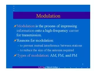
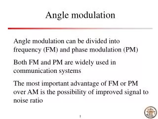
4.10 Summary and Discussion • Two kinds of angle modulation • Phase modulation (PM), where the instantaneous phase of the sinusoidal carrier wave is varied linearly with the message signal • Frequency modulation (FM), where the instantaneous frequency of the sinusoidal carrier wave is varied linearly with the message signal • Frequency modulation is typified by the equation • FM is a nonlinear modulation process • In FM, the carrier amplitude and therefore the transmitted average power is constant • Frequency modulation provides a practical method for the tradeoff of channel bandwidth for improved noise performance.