Chapter 10 Sinusoidal Steady State Analysis
Chapter 10 Sinusoidal Steady State Analysis. Chapter Objectives: Apply previously learn circuit techniques to sinusoidal steady-state analysis. Learn how to apply nodal and mesh analysis in the frequency domain.

Chapter 10 Sinusoidal Steady State Analysis
E N D
Presentation Transcript
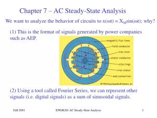
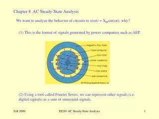
Chapter 10Sinusoidal Steady State Analysis Chapter Objectives: • Apply previously learn circuit techniques to sinusoidal steady-state analysis. • Learn how to apply nodal and mesh analysis in the frequency domain. • Learn how to apply superposition, Thevenin’s and Norton’s theorems in the frequency domain. • Learn how to analyze AC Op Amp circuits. • Be able to use PSpice to analyze AC circuits. • Apply what is learnt to capacitance multiplier and oscillators. Huseyin Bilgekul Eeng224 Circuit Theory II Department of Electrical and Electronic Engineering Eastern Mediterranean University
Steps to Analyze AC Circuits • Transform the circuit to the Phasor Domain. • Solve the problem using circuit techniques listed below • Nodal Analysis • Mesh Analysis • Superposition • Source transformation • Thevenin or Norton Equivalents • Transform the resulting circuit back to time domain.
Transformthe circuit to thephasor or frequency domain. Solvethe problem using circuit techniques (nodal analysis, mesh analysis, superposition, etc.). Transformthe resulting phasor to the time domain. Steps to Analyze AC Circuits Solve Variables in Freq Time to Freq Freq to Time
Nodal Analysis • Since KCL is valid for phasors, we can analyze AC circuits by NODAL analysis. • Determine the number of nodes within the network. • Pick a reference node and label each remaining node with a subscripted value of voltage: V1, V2 and so on. • Apply Kirchhoff’s current law at each node except the reference. Assume that all unknown currents leave the node for each application of Kirhhoff’s current law. • Solve the resulting equations for the nodal voltages. • For dependent current sources: Treat each dependent current source like an independent source when Kirchhoff’s current law is applied to each defined node. However, once the equations are established, substitute the equation for the controlling quantity to ensure that the unknowns are limited solely to the chosen nodal voltages.
Nodal Analysis • Since KCL is valid for phasors, we can analyze AC circuits by NODAL analysis. • Practice Problem 10.1: Find v1 and v2 using nodal analysis
Nodal Analysis • Practice Problem 10.1
Nodal Analysis • Practice Problem 10.1
Mesh Analysis • Since KVL is valid for phasors, we can analyze AC circuits by MESH analysis. • Practice Problem 10.4: Calculate the current Io Meshes 2 and 3 form a supermesh as shown in the circuit below.
Mesh Analysis • Practice Problem 10.4: Calculate the current Io
Mesh Analysis • Practice Problem 10.4: Calculate the current Io
Superposition Theorem • The superposition theorem eliminates the need for solving simultaneous linear equations by considering the effect on each source independently. • To consider the effects of each source we remove the remaining sources; by setting the voltage sources to zero (short-circuit representation) and current sources to zero (open-circuit representation). • The current through, or voltage across, a portion of the network produced by each source is then added algebraically to find the total solution for current or voltage. • The only variation in applying the superposition theorem to AC networks with independent sources is that we will be working with impedances and phasors instead of just resistors and real numbers. • The superposition theorem is not applicable to power effects in AC networks since we are still dealing with a nonlinear relationship. • It can be applied to networks with sources of different frequencies only if the total response for each frequency is found independently and the results are expanded in a nonsinusoidal expression . • One of the most frequent applications of the superposition theorem is to electronic systems in which the DC and AC analyses are treated separately and the total solution is the sum of the two.
Superposition Theorem When a circuit has sources operating at different frequencies, • The separate phasor circuit for each frequency must be solved independently, and • The total response is the sum of time-domain responses of all the individual phasor circuits.
Superposition Theorem a) All sources except DC 5-V set to zero • Superposition Theorem applies to AC circuits as well. • For sources having different frequencies, the total response must be obtained by adding individual responses in time domain. Exp. 10.6 Superposition Technique for sources having different frequencies b) All sources except 10cos(10t) set to zero
Superposition Theorem c) All sources except 2 sin 5t set to zero Exp. 10.6 Superposition Technique for sources having different frequencies vo= v1+ v2+ v3
Superposition Theorem P.P.10.6 Superposition Technique for sources having different Frequencies