Chapter 10 Sinusoidal Steady-State Analysis
Chapter 10 Sinusoidal Steady-State Analysis . Charles P. Steinmetz (1865-1923), the developer of the mathematical analytical tools for studying ac circuits. Courtesy of General Electric Co. Heinrich R. Hertz (1857-1894). Courtesy of the Institution of Electrical Engineers. cycles/second.

Chapter 10 Sinusoidal Steady-State Analysis
E N D
Presentation Transcript
Charles P. Steinmetz (1865-1923), the developer of the mathematical analytical tools for studying ac circuits. Courtesy of General Electric Co.
Heinrich R. Hertz (1857-1894). Courtesy of the Institution of Electrical Engineers. cycles/second Hertz, Hz
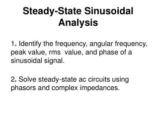
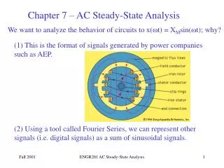
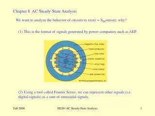
Sinusoidal Sources Amplitude Period = 1/f Phase angle Angular or radian frequency = 2pf = 2p/T Sinusoidal voltage source vsVm sin(t ). Sinusoidal current source isIm sin(t ).
Example v i circuit element + v _ i Voltage and current of a circuit element. The current leads the voltage by radians OR The voltage lags the current by radians
Example 10.3-1 Find their phase relationship and Therefore the current leads the voltage by
Recall Triangle for A and B of Eq. 10.3-4, where C .
Example 10.3-2 A B B A
Steady-State Response of an RL circuit An RL circuit. From #8	 Substitute the assumed solution into 10.4-1 Coeff. of cos Coeff. of sin Solve for A & B
Steady-State Response of an RL circuit (cont.) Thus the forced (steady-state) response is of the form
Complex Exponential Forcing Function Input Response magnitude phase frequency Exponential Signal Note
Complex Exponential Forcing Function (cont.) try We get where
Complex Exponential Forcing Function (cont.) Substituting for A We expect
Example We replace Substituting ie
Example(cont.) The desired answer for the steady-state current interchangeable Or
Using Complex Exponential Excitation to Determine a Circuit’s SS Response to a Sinusoidal Source • Write the excitation as a cosine waveform with • a phase angle • Introduce complex excitation • Use the assumed response • Determine the constant A
Obtain the solution • The desired response is Example 10.5-1
Example 10.5-1(cont.) The solution is The actual response is
The Phasor Concept A sinusoidal current or voltage at a given frequency is characterized by its amplitude and phase angle. Magnitude Phase angle Thus we may write unchanged
The Phasor Concept(cont.) A phasor is a complex number that represents the magnitude and phase of a sinusoid. phasor The Phasor Concept may be used when the circuit is linear , in steady state, and all independent sources are sinusoidal and have the same frequency. A real sinusoidal current phasor notation
The Transformation Time domain Transformation Frequency domain
The Transformation (cont.) Time domain Transformation Frequency domain
Example Substitute into 10.6-2 Suppress
Phasor Relationship for R, L, and C Elements Time domain Resistor Frequency domain Voltage and current are in phase
Inductor Time domain Frequency domain Voltage leads current by
Capacitor Time domain Frequency domain Voltage lags current by
Impedance and Admittance Impedance is defined as the ratio of thephasor voltage to the phasor current. Ohm’s law in phasor notation phase magnitude or polar exponential rectangular
Graphical representation of impedance R Resistor wL Inductor Capacitor 1/wC
Admittance is defined as the reciprocal ofimpedance. conductance In rectangular form susceptance G Resistor 1/wL Inductor wC Capacitor
Kirchhoff’s Law using Phasors KVL KCL Both Kirchhoff’s Laws hold in the frequency domain. and so all the techniques developed for resistive circuits hold • Superposition • Thevenin &Norton Equivalent Circuits • Source Transformation • Node & Mesh Analysis • etc.
Impedances in series Admittances in parallel
Node Voltage & Mesh Current using Phasors va = ? vb = ?
KCL at node a KCL at node b Rearranging Admittance matrix
If Im = 10 A and Using Cramer’s rule to solve for Va Therefore the steady state voltage va is
Example 10.10-1 v = ? use supernode concept as in #4
Example 10.10-1 (cont.) KCL at supernode Rearranging
Example 10.10-1 (cont.) Therefore the steady state voltage v is
Example 10.10-2 (cont.) KVL at mesh 1 & 2 Using Cramer’s rule to solve for I1
Superposition, Thevenin & Norton Equivalents and Source Transformations Example 10.11-1 i = ? Consider the response to the voltage source acting alone = i1
Example 10.11-2 (cont.) Substitute
Example 10.11-2 (cont.) Consider the response to the current source acting alone = i2 Using the principle of superposition