Download
1 / 24
240 likes | 625 Vues
Chap. 10 Sinusoidal Steady-State Power Calculations. C ontents. 10.1 Instantaneous Power 10.2 Average and Reactive Power 10.3 The rms Value and Power Calculations 10.4 Complex Power 10.5 Complex Power Calculations 10.6 Maximum Power Transfer. Objectives. 1. 了解交流功率觀念、相互關係及如何計算:

E N D
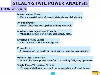
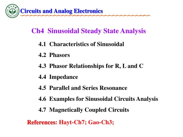
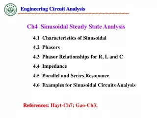
Chap.10 Sinusoidal Steady-State Power Calculations Contents 10.1 Instantaneous Power 10.2 Average and Reactive Power 10.3 The rms Value and Power Calculations 10.4 Complex Power 10.5 Complex Power Calculations 10.6 Maximum Power Transfer Objectives 1. 了解交流功率觀念、相互關係及如何計算: ◆ 瞬時功率 ◆ 平均(實)功率 ◆ 無效功率(虛功率) ◆ 複數功率 ◆ 功率因數 2. 了解最大實功率傳送至一交流電路負載之情況,並能計算 在此條件下之負載阻抗。 3. 在具有線性變壓器及理想變壓器之交流電路中,能計算所 有形式之交流功率。
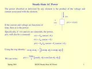
10.1 Instantaneous Power 兩倍頻 定值 或 瞬時功率 p = vi 利用三角恆等式: 2 2
10.2 Average and Reactive Power 因純電阻電路之v = i,故可簡化為 且稱為瞬時實功率(instantaneous real power)。 P: 平均功率(實功率) Average (Real) Power 其中 注意: Q : 無效功率(虛功率) Reactive Power 單位(Units):瓦(watt,W) forPand 乏(volt-amp reactive, or VAR)forQ Power for Purely Resistive Circuits 3 3
Power for Purely Inductive Circuits 因對一純電感性電路而言,其電流落後電壓之相位角90°,即i= v - 90°,故可簡化為 且其平均功率為零。 因對一純電容性電路而言,其電流領先電壓之相位角90°,即i= v + 90°,故可簡化為 且其平均功率為零。 Power for Purely Capacitive Circuits 4
The Power Factor 功率因數(power factor): 無效功率因數(reactive factor): 功率因數角(power factor angle): v- i • 由於 cos (v - i ) = cos (i- v ),無法明確描述功率因數角。故用 • 落後功率因數(lagging power factor) 表示電流落後電壓相位角, 屬電感性。 • 領先功率因數(leading power factor) 表示電流領先電壓相位角, 屬電容性。 5
EX 10.1 Calculating Average and Reactive Power (a) (b) By the passive sign convention, the negative value of −100 W means that the network inside the box is deliveringaverage power to the terminals. (c) Because Q is positive, the network inside the box is absorbingmagnetizing vars at its terminals. 6
EX 10.2 Power Calculations Involving Household Appliances The branch circuit supplying the outlets in a typical home kitchen is wired with #12 conductor and is protected by either a 20 A fuse or a 20 A circuit breaker. Assume that the following 120 V appliances are in operation at the same time: a coffeemaker, egg cooker, frying pan, and toaster. Will the circuit be interrupted by the protective device? > 20 A Yes, the protective device will interrupt the circuit. 7
10.3 The rms Value and Power Calculations The effective value of vs(100 V rms) delivers the same power to Ras the dc voltage Vs(100 V dc). 弦波電源之rms值又稱為有效值。 OR, i = 平均功率及無效功率亦可用有效值表示 8 8
EX 10.3 Determining Average Power Delivered to a Resistor by Sinusoidal Voltage The phasor transform of a sinusoidal function may also be expressed in terms of the rms value. The magnitude of the rms phasor is equal to the rms value of the sinusoidal function. If a phasor is based on the rms value, we indicate this by either “rms” or the subscript “eff” adjacent to the phasor quantity. A sinusoidal voltage having a maximum amplitude of 625 V is applied to the terminals of a 50 resistor. (a) Find the average power delivered to the resistor. (a) (b) Repeat (a) by first finding the current in the resistor. (b) 9
10.4 Complex Power 複數功率(complex power): 伏安 (VA) 功率三角形 Power Triangle 視在功率 10
EX 10.4 Calculating Complex Power Laggingpf:Q> 0 An electrical load operates at 240 V rms. The load absorbs an average power of 8 kW at a lagging power factor of 0.8. a) Calculate the complex power of the load. b) Calculate the impedance of the load. (a) (b) Also, 11
10.5 Complex Power Calculations Also 複數功率 =(均方根相量電壓) × (均方根相量電流共軛值) 注意: 12
Alternate Forms for Complex Power 若Z為純電阻元件時 若Z為純電抗元件時 (a) (b) 13
EX 10.5 Calculating Average and Reactive Power supplying a) Calculate the load current IL and voltage VL . b) Calculate the average and reactive power delivered to the load. c) Calculate the average and reactive power delivered to the line. d) Calculate the average and reactive power supplied by the source. 或 14
EX 10.6 Calculating Average and Reactive Power Load 1 absorbs an average power of 8 kW at a leading power factor of 0.8. Load 2 absorbs 20 kVA at a lagging power factor of 0.6. a) Determine the power factor of the two loads in parallel. 15
EX 10.6 Calculating Average and Reactive Power (Contd.) b) Determine the apparent power required tosupply the loads, the magnitude of the current,Is, and the average power loss in the transmissionline. c) Given that f = 60 Hz,compute the value of the capacitor that wouldcorrect the power factor to 1 if placed in parallelwith the two loads. Recompute the valuesin b) for the load with the corrected powerfactor. 16
EX 10.7 Balancing Power Delivered with Power Absorbed (a) (b) (c) 17
10.6 Maximum Power Transfer 最大功率轉移之條件 利用微分極值定理之觀念,想得到P的最大值的條件為 和 均為零。 Let Also, = 0 = 0 18
The Maximum Average Power Absorbed 在 之條件下,負載電流為VTh/2RL,故傳送至負載之最大平均功率 若將載維寧等效電壓改以電壓峯值表示,則 當Z受限制時之最大功率轉移: (a) 若RL及XL被限制在某一範圍時,應先考慮將XL儘可能調到接近-XTh,則 (b) 若ZL的大小可改變,但其相位角不可改變時,則在 時,負載可 得到最大功率轉移。 Problem 10.32 19
EX 10.9 Maximum Power Transfer with ZLRestrictions b) Restrictions on the load impedance: a) No Restrictions on the load impedance. Set XCas close to −4000 as possible. Set 21
EX 10.10Max Power Transfer with Impedance Angle Restrictions Restrictions on the load impedance: Phase angle = −36.87◦ 22
EX 10.11 A Circuit with an Ideal Transformer The variable resistor is adjusted until maximum average power is delivered to RL . a) What is the value of RL in ohms? b) What is the maximum average power (in watts) delivered to RL? Open circuit: I2 = 0, hence I1 = 0. 23
EX 10.11 A Circuit with an Ideal Transformer (Contd.) 網目方程式: 24