Chapter 5 Steady-State Sinusoidal Analysis
Chapter 5 Steady-State Sinusoidal Analysis. Electrical Engineering and Electronics II. Scott. 2008.10. Main Contents. 1. Identify the frequency, angular frequency, peak value, rms value, and phase of a sinusoidal signal.

Chapter 5 Steady-State Sinusoidal Analysis
E N D
Presentation Transcript
Chapter 5 Steady-State Sinusoidal Analysis Electrical Engineering and Electronics II Scott 2008.10
Main Contents 1. Identify the frequency, angular frequency, peak value, rms value, and phase of a sinusoidal signal. 2. Solve steady-state ac circuits using phasors and complex impedances. 3. Compute power for steady-state sinusoidal ac circuits.
Main Contents 4. Find Thévenin equivalent circuits for steady-state ac circuits. 5. Determine load impedances for maximum power transfer. 6. Solve balanced three-phase circuits.
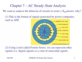
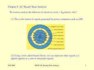
The importance of steady-state sinusoidal analysis • Electric power transmission and distribution by sinusoidal currents and voltages • Sinusoidal signals in radio communication • All periodic signals are composed of sinusoidal components according to Fourier analysis
Parameters of Sinusoidal Currents and Voltages • Vmis the peak value, unit is volt • ω is the angular frequency, unit is radians per second • f is the frequency,unit is Hertz (Hz) or inverse second. • θ is the phase angle, unit is radian or degree.
Parameters of Sinusoidal Currents and Voltages Frequency Angular frequency To uniformity, This textbook expresses sinusoidal functions by using cosine function rather than the sine function. 。
Average Power Root-Mean-Square Values or Effective Values
RMS Value of a Sinusoid The rms value for a sinusoid is the peak value divided by the square root of two. However, this is not true for other periodic waveforms such as square waves or triangular waves.
A voltage given by is applied to a 50Ω resistance. Find the rms value of the voltage and the average power delivered to the resistance.
Complex Numbers • 3 forms of complex numbers • Arithmetic operations of complex numbers
Rectangular form Im b |A| Re a 0 • Imaginary unit • Real part • Imaginary part • Magnitude • Angle • Conjugate
Im b |A| Re a 0 • Polar form • Conversion between Rectangular and polar
Im b |A| Re a 0 • Exponential form • Euler’s Identity
Rectangular form Polar form Exponential form • Three forms
Arithmetic Operations Given • Identity • Adding and subtracting
Arithmetic Operations Given • Product
Arithmetic Operations Given • Dividing
Phasor Definition 5.2 PHASORS Sinusoidal steady-state analysis is greatly facilitated if currents and voltages are represented as vectors or Phasors. • rms Phasor or effective phasor. • In this book, if phasors are not labeled as rms, then they are peak phasors.
Phasors as Rotating Vector Angular velocity 正弦量可以表示为在复平面complex plane上按逆时针方向旋转的相量的实部real part。
θ • Sinusoids can be visualized as the real-axis projection of vectors rotating in the complex plane. • The phasor for a sinusoid is a ‘snapshot’ of the corresponding rotating vector at t = 0.
Phase Relationships • To determine phase relationships from a phasor diagram, consider the phasors to rotate counterclockwise. • Then when standing at a fixed point, if V1 arrives first followed by V2 after a rotation of θ , we say that V1leads V2 by θ . • Alternatively, we could say that V2lags V1 by θ . (Usually, we take θ≤180oas the smaller angle between the two phasors.)
Adding Sinusoids Using Phasors Step 1: Determine the phasor for each term Step 2: Add the phasors using complex arithmetic. Step 3: Convert the sum to polar form. Step 4: Write the result as a time function.
Adding Sinusoids Using Phasors • Example: Solution:
Exercise • Adding Sinusoids Using Phasors • Answers
5.3 COMPLEX IMPEDANCES • By using phasors to represent sinusoidal voltages and currents, we can solve sinusoidal steady-state circuit problems with relative ease. • Sinusoidal steady-state circuit analysis is virtually the same as the analysis of resistive circuits except for using complex arithmetic.
U I u i t 0 Sinusoidal response of resistance • Relationship between voltage and current then:
Sinusoidal response of resistance • 2.Phasor relation and diagram Substituting for current and voltage phasors Phasor diagram
Sinusoidal response of resistance Plot the phasor diagram phasors expression in Ohm’s Law
Sinusoidal response of resistance • Power Instantaneous power No doubt, p≥0,Resistance always absorbs energy.
p VrmsIrms t 0 i v • Sinusoidal response of resistance • Power 2VrmsIrms
Sinusoidal response of resistance • Power Average Power ——Average value of instantaneous power in a period Average Power represents the consumed power, is also named as Real power.
ωt 0 Sinusoidal response of Inductance • Relationship between voltage and current u、i have the same frequency,u leads i by 90o u π 2π
Sinusoidal response of Inductance • Effective Value Reactance电抗-感抗 Definition
i jωL L v Sinusoidal response of Inductance Phasor diagram: • Phasor relations Complex impedance
p VrmsIrms u i t 0 Sinusoidal response of Inductance • Power
u i t 0 i i i i u UI u u u p t 0 Sinusoidal response of Inductance • Power ——magnitude of magnetic field increases,inductance absorbs energy 释放能量 释放能量 ——magnitude of magnetic field decreases,inductance supplys energy 吸收能量 吸收能量
Sinusoidal response of Inductance Average Power • Power • Inductance is an energy-storage element rather than an energy-consuming element
Sinusoidal response of Inductance Reactive Power The power flows back and forth to inductances and capacitances is called reactive power Q, it is the peak instantaneous power。 Unit: Var (乏) Reactive power is important because it causes power dissipation in the lines and transformers of a power distribution system. Specific Charge is executed by electric-power companies for reactive power.
i C v i 2 0 Sinusoidal response of capacitance • Relationship between voltage and current Current leads voltage by 90°
i C v Sinusoidal response of capacitance • Relationship between voltage and current Reactance电抗-容抗 Definition
i C v -jωC Sinusoidal response of capacitance • Phasor diagram
UrmsIrms p u i t 0 Sinusoidal response of capacitance • Power • Instantaneous power
u i t i 0 u i UI u p i i t u u 0 Sinusoidal response of capacitance • Power ——capacitance charges,it absorbs energy 释放能量 释放能量 ——capacitance discharges,it supplys energy 吸收能量 吸收能量
Sinusoidal response of capacitance • Power Average Power • Capacitance is an energy-storage element rather than an energy-consuming element.
Sinusoidal response of capacitance • Power Reactive Power • Assuming the same current acts on the inductance and capacitance respectively, the initial phase is 0,then