Single-cycle datapath, slightly rearranged
260 likes | 468 Vues
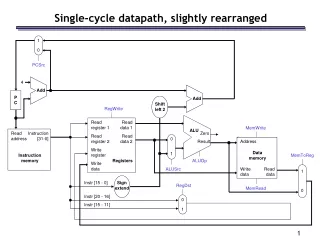
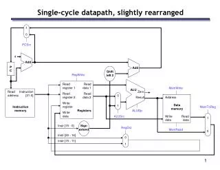
Add. Add. Single-cycle datapath, slightly rearranged. 1 0. PCSrc. 4. P C. Shift left 2. RegWrite. Read register 1. Read data 1. MemWrite. ALU. Read address. Instruction [31-0]. Zero. Read register 2. Read data 2. 0 1. Result. Address. Write register. Data

Single-cycle datapath, slightly rearranged
E N D
Presentation Transcript
Add Add Single-cycle datapath, slightly rearranged 1 0 PCSrc 4 P C Shift left 2 RegWrite Read register 1 Read data 1 MemWrite ALU Read address Instruction [31-0] Zero Read register 2 Read data 2 0 1 Result Address Write register Data memory Instruction memory MemToReg Registers ALUOp Write data ALUSrc Write data Read data 1 0 Instr [15 - 0] Sign extend RegDst MemRead Instr [20 - 16] 0 1 Instr [15 - 11]
Pipeline registers • In pipelining, we divide instruction execution into multiple cycles • IF ID EX MEM WB • Information computed during one cycle may be needed in a later cycle: • Instruction read in IF stage determines which registers are fetched in ID stage, what immediate is used for EX stage, and what destination register is for WB • Register values read in ID are used in EX and/or MEM stages • ALU output produced in EX is an effective address for MEM or a result for WB • A lot of information to save! • Saved in intermediate registers called pipeline registers • The registers are named for the stages they connect: IF/ID ID/EX EX/MEM MEM/WB • No register is needed after the WB stage, because after WB the instruction is done
0 1 Add Add Shift left 2 Pipelined datapath 1 0 PCSrc 4 IF/ID ID/EX EX/MEM MEM/WB P C RegWrite Read register 1 Read data 1 MemWrite ALU Read address Instruction [31-0] Zero Read register 2 Read data 2 0 1 Result Address Write register Data memory Instruction memory MemToReg Registers ALUOp Write data ALUSrc Write data Read data 1 0 Instr [15 - 0] Sign extend RegDst MemRead Instr [20 - 16] Instr [15 - 11]
Propagating values forward • Data values required later propagated through the pipeline registers • The most extreme example is the destination register (rd or rt) • It is retrieved in IF, but isn’t updated until the WB • Thus, it must be passed through all pipeline stages, as shown in red on the next slide • Notice that we can’t keep a single “instruction register,” because the pipelined machine needs to fetch a new instruction every clock cycle
Add Add Shift left 2 The destination register 1 0 PCSrc 4 IF/ID ID/EX EX/MEM MEM/WB P C RegWrite Read register 1 Read data 1 MemWrite ALU Read address Instruction [31-0] Zero Read register 2 Read data 2 0 1 Result Address Write register Data memory Instruction memory MemToReg Registers ALUOp Write data ALUSrc Write data Read data 1 0 Instr [15 - 0] Sign extend RegDst MemRead Instr [20 - 16] 0 1 Instr [15 - 11]
What about control signals? • Control signals generated similar to the single-cycle processor • in the ID stage, the processor decodes the instruction fetched in IF and produces the appropriate control values • Some of the control signals will not be needed until later stages • These signals must be propagated through the pipeline until they reach the appropriate stage • We just pass them in the pipeline registers, along with the data • Control signals can be categorized by the pipeline stage that uses them
0 1 Add Add Shift left 2 Pipelined datapath and control 1 0 ID/EX EX/MEM WB PCSrc WB Control MEM/WB M 4 IF/ID EX M WB P C RegWrite Read register 1 Read data 1 MemWrite ALU Read address Instruction [31-0] Zero Read register 2 Read data 2 0 1 Result Address Write register Data memory Instruction memory MemToReg Registers ALUOp Write data ALUSrc Write data Read data 1 0 Instr [15 - 0] Sign extend RegDst MemRead Instr [20 - 16] Instr [15 - 11]
An example execution sequence • Here’s a sample sequence of instructions to execute 1000: lw $8, 4($29) 1004: sub $2, $4, $5 1008: and $9, $10, $11 1012: or $16, $17, $18 1016: add $13, $14, $0 • We’ll make some assumptions, just so we can show actual data values: • Each register contains its number plus 100. For instance, register $8 contains 108, register $29 contains 129, etc. • Every data memory location contains 99 • Our pipeline diagrams will follow some conventions: • An X indicates values that aren’t important, like the constant field of an R-type instruction • Question marks ??? indicate values we don’t know, usually resulting from instructions coming before and after the ones in our example addresses in decimal
0 1 1 0 ID/EX EX/MEM WB Add Add PCSrc Control MEM/WB M WB Shift left 2 4 IF/ID EX M WB 1004 P C RegWrite (?) ??? ??? ??? Read register 1 Read data 1 1000 MemWrite (?) ALU Read address Instruction [31-0] Zero ??? ??? Read register 2 Read data 2 ??? ??? 0 1 Result Address ??? Write register MemToReg (?) ??? Data memory Instruction memory Registers ALUOp (???) ??? Write data ??? ??? ALUSrc (?) Write data Read data 1 0 Sign extend ??? ??? RegDst (?) ??? MemRead (?) ??? ??? ??? ??? ??? ??? ??? ??? Cycle 1 (filling) IF: lw $8, 4($29) ID: ??? EX: ??? MEM: ??? WB: ???
1 0 0 1 ID/EX EX/MEM WB Add Add PCSrc Control MEM/WB M WB Shift left 2 4 IF/ID EX M WB 1008 P C RegWrite (?) 129 29 ??? Read register 1 Read data 1 1004 MemWrite (?) ALU Read address Instruction [31-0] Zero X X ??? Read register 2 Read data 2 ??? 0 1 Result Address ??? Write register MemToReg (?) ??? Data memory Instruction memory Registers ALUOp (???) ??? Write data ??? ??? ALUSrc (?) Write data Read data 1 0 4 Sign extend ??? RegDst (?) ??? MemRead (?) 8 ??? ??? ??? ??? X ??? ??? Cycle 2 IF: sub $2, $4, $5 ID: lw $8, 4($29) EX: ??? MEM: ??? WB: ???
0 1 1 0 ID/EX EX/MEM WB Add Add PCSrc Control MEM/WB M WB Shift left 2 4 IF/ID EX M WB 1012 P C RegWrite (?) 104 4 129 Read register 1 Read data 1 1008 MemWrite (?) ALU Read address Instruction [31-0] Zero 5 X 10⁵ Read register 2 Read data 2 ??? 0 1 Result Address 4 133 Write register MemToReg (?) ??? Data memory Instruction memory Registers ALUOp (add) ??? Write data ??? ??? ALUSrc (1) Write data Read data 1 0 X Sign extend 4 RegDst (0) MemRead (?) ??? X 8 ??? ??? 8 2 X ??? Cycle 3 IF: and $9, $10, $11 ID: sub $2, $4, $5 EX: lw $8, 4($29) MEM: ??? WB: ???
1 0 0 1 ID/EX EX/MEM WB Add Add PCSrc Control MEM/WB M WB Shift left 2 4 IF/ID EX M WB 1016 P C RegWrite (?) 110 10 104 Read register 1 Read data 1 1012 MemWrite (0) ALU Read address Instruction [31-0] Zero 11 105 111 Read register 2 Read data 2 133 0 1 Result Address –1 Write register MemToReg (?) ??? Data memory Instruction memory Registers ALUOp (sub) ??? Write data 99 ??? ALUSrc (0) Write data Read data X 1 0 X Sign extend X RegDst (1) ??? MemRead (1) X X 2 8 ??? 9 2 ??? Cycle 4 IF: or $16, $17, $18 ID: and $9, $10, $11 EX: sub $2, $4, $5 MEM: lw $8, 4($29) WB: ???
1 0 0 1 ID/EX EX/MEM WB Add Add PCSrc Control MEM/WB M WB Shift left 2 4 IF/ID EX M WB 1020 P C RegWrite (1) 117 17 110 Read register 1 Read data 1 1016 MemWrite (0) ALU Read address Instruction [31-0] Zero 18 111 118 Read register 2 Read data 2 -1 0 1 Result Address 8 Write register MemToReg (1) 110 Data memory Instruction memory Registers ALUOp (and) 99 Write data X 99 ALUSrc (0) Write data Read data 105 1 0 X Sign extend X RegDst (1) 133 MemRead (0) X X 9 2 8 16 9 99 Cycle 5 (full) IF: add $13, $14, $0 ID: or $16, $17, $18 EX: and $9, $10, $11 MEM: sub $2, $4, $5 WB: lw $8, 4($29)
1 0 0 1 ID/EX EX/MEM WB Add Add PCSrc Control MEM/WB M WB Shift left 2 4 IF/ID EX M WB ??? P C RegWrite (1) 114 14 117 Read register 1 Read data 1 1020 MemWrite (0) ALU Read address Instruction [31-0] Zero 0 118 0 Read register 2 Read data 2 110 0 1 Result Address 119 2 Write register MemToReg (0) Data memory Instruction memory Registers ALUOp (or) -1 Write data X X ALUSrc (0) Write data Read data 111 1 0 X Sign extend X RegDst (1) -1 MemRead (0) X X 16 9 2 13 16 -1 Cycle 6 (emptying) IF: ??? ID: add $13, $14, $0 EX: or $16, $17, $18 MEM: and $9, $10, $11 WB: sub $2, $4, $5
1 0 0 1 ID/EX EX/MEM WB Add Add PCSrc Control MEM/WB M WB Shift left 2 4 IF/ID EX M WB ??? P C RegWrite (1) ??? ??? 114 Read register 1 Read data 1 ??? MemWrite (0) ALU Read address Instruction [31-0] Zero ??? 0 ??? Read register 2 Read data 2 119 0 1 Result Address 9 Write register MemToReg (0) 114 Data memory Instruction memory Registers ALUOp (add) 110 Write data X X ALUSrc (0) Write data Read data 118 1 0 ??? Sign extend X RegDst (1) MemRead (0) 110 ??? X 13 16 9 ??? 13 110 Cycle 7 IF: ??? ID: ??? EX: add $13, $14, $0 MEM: or $16, $17, $18 WB: and $9, $10, $11
1 0 0 1 ID/EX EX/MEM WB Add Add PCSrc Control MEM/WB M WB Shift left 2 4 IF/ID EX M WB ??? P C RegWrite (1) ??? ??? ??? Read register 1 Read data 1 ??? MemWrite (0) ALU Read address Instruction [31-0] Zero ??? ??? ??? Read register 2 Read data 2 114 0 1 Result Address 16 Write register MemToReg (0) ??? Data memory Instruction memory Registers ALUOp (???) 119 Write data X X ALUSrc (?) Write data Read data 0 1 0 ??? Sign extend ??? RegDst (?) MemRead (0) 119 ??? ??? 13 16 ??? ??? ??? 119 Cycle 8 IF: ??? ID: ??? EX: ??? MEM: add $13, $14, $0 WB: or $16, $17, $18
1 0 0 1 ID/EX EX/MEM WB Add Add PCSrc Control MEM/WB M WB Shift left 2 4 IF/ID EX M WB ??? P C RegWrite (1) ??? ??? ??? Read register 1 Read data 1 ??? MemWrite (?) ALU Read address Instruction [31-0] Zero ??? ??? ??? Read register 2 Read data 2 ??? 0 1 Result Address 13 Write register MemToReg (0) ??? Data memory Instruction memory Registers ALUOp (???) 114 Write data X X ALUSrc (?) Write data Read data ? 1 0 ??? Sign extend ??? RegDst (?) 114 MemRead (?) ??? ??? ??? 13 ??? ??? ??? 114 Cycle 9 IF: ??? ID: ??? EX: ??? MEM: ??? WB: add $13, $14, $0
That’s a lot of diagrams there • Compare the last few slides with the pipeline diagram above • You can see how instruction executions are overlapped • Each functional unit is used by a different instruction in each cycle • The pipeline registers save control and data values generated in previous clock cycles for later use • When the pipeline is full in clock cycle 5, all of the hardware units are utilized. This is the ideal situation, and what makes pipelined processors so fast • See the textbook for more examples
Instruction set architectures and pipelining • The MIPS instruction set was designed especially for easy pipelining: • All instructions are 32-bits long, so the instruction fetch stage just needs to read one word on every clock cycle • Fields are in the same position in different instruction formats—the opcode is always the first six bits, rs is the next five bits, etc. This makes things easy for the ID stage • MIPS is a register-to-register architecture, so arithmetic operations cannot contain memory references. This keeps the pipeline shorter and simpler • Pipelining is harder for older/more complex instruction sets: • If different instructions had different lengths or formats, the fetch and decode stages would need extra time to determine the actual length of each instruction and the position of the fields • With memory-to-memory instructions, additional pipeline stages may be needed to compute effective addresses and read memory before the EX stage
0 1 Add Add Shift left 2 Note how everything goes left to right, except … 1 0 PCSrc 4 IF/ID ID/EX EX/MEM MEM/WB P C RegWrite Read register 1 Read data 1 MemWrite ALU Read address Instruction [31-0] Zero Read register 2 Read data 2 0 1 Result Address Write register Data memory Instruction memory MemToReg Registers ALUOp Write data ALUSrc Write data Read data 1 0 Instr [15 - 0] Sign extend RegDst MemRead Instr [20 - 16] Instr [15 - 11]
An example with dependencies sub $2, $1, $3 and $12, $2, $5 or $13, $6, $2 add $14, $2, $2 sw $15, 100($2) • There are several dependencies in this new code fragment • the first instruction, SUB, stores a value into $2 • that register is used as a source in the rest of the instructions • This is not a problem for the single-cycle datapath • each instruction is executed completely before the next one begins, so instructions 2 through 5 above use the new value of $2 • How would this code sequence fare in our 5-stage MIPS pipeline?
Data hazards in the pipeline diagram • The sub instruction does not write to register $2 until clock cycle 5. This causes two data hazards in our current pipelined datapath: • the and reads register $2 in cycle 3, and since sub hasn’t modified the register yet, this will be the old value of $2, not the new one • the or instruction uses register $2 in cycle 4, again before it’s actually updated by sub
Things that are okay • The add instruction is okay, because of the register file design • registers are written at the beginning of a clock cycle • the new value will be available by the end of that cycle • The sw is no problem at all, since it reads $2 after the sub finishes
Dependency arrows • Arrows indicate the flow of data between instructions • The tails of the arrows show when register $2 is written • The heads of the arrows show when $2 is read • Any arrow that points backwards in time represents a data hazard in our basic pipelined datapath
Bypassing the register file • The actual result $1 - $3 is computed in clock cycle 3, before it is needed in cycles 4 and 5 • If we could somehow bypass the writeback and register read stages when needed, then we can eliminate these data hazards • Essentially, we need to pass the ALU output from sub directly to the and and or instructions, without going through the register file
0 1 PC IF/ID ID/EX EX/MEM MEM/WB ALU Registers Instruction memory Data memory 1 0 Rt Rd Pipleline Registers to the rescue! • Pipeline stages communicate through pipeline registers: IF/ID ID/EX EX/MEM MEM/WB • We “forward” data from pipeline registers to later instructions ALU output available here