Download
1 / 25
250 likes | 400 Vues
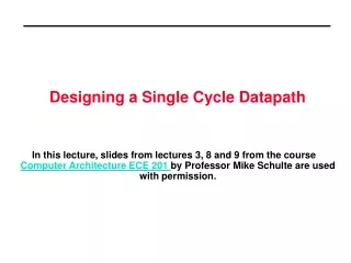
CDA 3101 Fall 2013 Introduction to Computer Organization. Single-Cycle Datapath 7 October 2013. Review. Construction of the Datapath Instruction-specific building blocks (R, I, J formats) Modular design ALU, Register File, Data Memory

E N D
CDA 3101 Fall 2013Introduction to Computer Organization Single-Cycle Datapath 7 October 2013
Review • Construction of the Datapath • Instruction-specific building blocks (R, I, J formats) • Modular design • ALU, Register File, Data Memory • ALU or adder for computing branch target address (BTA) • Instruction-specific connection of datapath components • Instruction Formats and the Datapath • R: ALU operation, • I: Load/store - Data I/O from register file/memory • I: Conditional branch – Eval. condition, Compute BTA • J: Jump (unconditional branch) – Compute JTA
Overview of Today’s Lecture • Can we make a datapath operate in one cycle? • All instructions executed in CPI = 1 • Increases efficiency of software • Composition of simple datapath components • Build up the datapath iteratively • R-format instruction • I-format • J-format • Problems with the single-cycle assumption
Processor Performance CPU time =IC* CPI *Cycle time Program Compiler ISA Microarchitecture Hardware
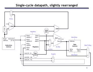
Implementation Review Data Instruction memory rd Data memory rs Address Registers PC ALU Address rt Instruction +4 Data imm Opcode, funct Controller • Datapath is based on register transfers required to execute instructions • Control causes the right transfers to happen at the right time
Component: R-format Datapath ALU op Register File 3 Read Reg 1 Read Reg 2 Write Register Write Data Read Data 1 Read Data 2 Instruction ALU Register Write • Format:opcode r1, r2, r3 Zero Result
Component: Load/Store Datapath Fetch DecodeExecute
Component: Branch Datapath Fetch DecodeExecute
R-formatDatapath Actions Instruction:add $t0, $t1, $t2 • Fetch instruction and increment PC • Input $t0 and $t1 from Register File • ALU operates on $t0 and $t1, per the funct field of the MIPS instruction (Bits 5-0) • Result from ALU written to Register File using bits 15-11 of instruction to select destination register (e.g., $t0).
Load/StoreDatapath Actions Instruction:lw $t1, offset($t2) • Fetch instruction and increment PC • Read register value (e.g., base address in $t2) from Register File • ALU adds value from $t2 to sign-extended lower 16 bits of the instruction (i.e., offset) • Result from ALU = address to Data Memory • Retrieve data from memory, write to Register File, per register number in $t1 (Bits 20-16)
R-format + Load/Store Datapath Fetch DecodeExecute
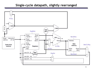
BranchDatapath Actions Instruction:beq $t1, $t2, offset • Fetch instruction and increment PC • Read registers (e.g., $t1 and $t2) from the register file from Register File • ALU subtracts $t1 - $t2. Adder sums PC + 4 plus sign-extended lower 16 bits of offset shifted left two bits => branch target address • ALU’s Zero output directs PC+4 or BTA to be written as new PC
R-format + Load/Store + Branch DP Fetch DecodeExecute
ALU Control Codes ALU has two control codes (total = 5 bits): • ALUop – Selects specific ALU operation • Control Input – Selects ALU functionality
ALU Control Bits ALU has the following control bits: So where do these control bits come from?
Datapath with WriteReg Control Extra Mux
Datapath with Control Signals ALU Control
Datapath Extension: Jump Instr. Instruction:j address • Fetch instruction and increment PC • Read address from immediate field of instr. • Jump target address (JTA) has these bits: • Bits 31-28: Upper four bits of PC+4 • Bits 27-02: Immediate field of Jump instr. • Bits 01-00: Zero (002) • Mux controlled by Jump Control Bit selects JTA or branch target address as new PC
Datapath Extension: Jump Instr. • Bits 31-28: Upper four bits of (PC + 4) • Bits 27-02: Immediate field of jump instruction • Bits 01-00: Zero (002) - Word alignment
Datapath Extension:Jump Instr. Jump Control JTA
Problems • Can we make a datapath operate in one cycle? • All instructions executed in CPI = 1 • Increases efficiency of software in MIPS • Problems with single-cycle datapath • Propagation delay for 1-5 components • No phased execution: Must settle in 1 clock cycle • Maximum delay = Load instruction (5 components) • Increases clock cycle time • Decreased Performance tcpu = IC * CPI * tcyc
Conclusions • Can we make a datapath operate in one cycle? • Yes – “Some design required” • Do we want a single-cycle datapath? - No! Increases cycle time ( tcyc=> tcpu) • Build up the datapath w/ different instructions • ALU operations, Load, Store, Branch • Can add new instructions (Jump) • New instructions = more HW HIGHER COST