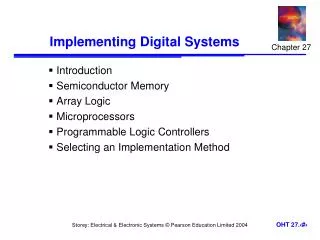
Quantization in Implementing Systems
This document explores the effects of coefficient quantization in both Infinite Impulse Response (IIR) and Finite Impulse Response (FIR) systems. It examines how quantization affects system stability, pole-zero configurations, and the consequent frequency response. A detailed sensitivity analysis is required to understand how quantization errors can lead to instability or deviation from expected performance, especially in systems with tightly clustered roots and narrow bandwidths. Strategies are provided for mitigating round-off noise and avoiding limit cycles in digital filters.

Quantization in Implementing Systems
E N D
Presentation Transcript
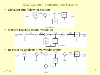
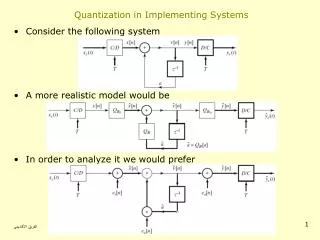
Quantization in Implementing Systems • Consider the following system • A more realistic model would be • In order to analyze it we would prefer لجنة الهندسة الكهربائية
Effects of Coefficient Quantization in IIR Systems • When the parameters of a rational system are quantized • The poles and zeros of the system function move • If the system structure of the system is sensitive to perturbation of coefficients • The resulting system may no longer be stable • The resulting system may no longer meet the original specs • We need to do a detailed sensitivity analysis • Quantize the coefficients and analyze frequency response • Compare frequency response to original response • We would like to have a general sense of the effect of quantization لجنة الهندسة الكهربائية
Effects on Roots • Each root is affected by quantization errors in ALL coefficient • Tightly clustered roots can be significantly effected • Narrow-bandwidth lowpass or bandpass filters can be very sensitive to quantization noise • The larger the number of roots in a cluster the more sensitive it becomes • This is the reason why second order cascade structures are less sensitive to quantization error than higher order system • Each second order system is independent from each other Quantization لجنة الهندسة الكهربائية
Poles of Quantized Second-Order Sections • Consider a 2nd order system with complex-conjugate pole pair • The pole locations after quantization will be on the grid point 3-bits 7-bits لجنة الهندسة الكهربائية
Coupled-Form Implementation of Complex-Conjugate Pair • Equivalent implementation of the second order system • But the quantization grid this time is لجنة الهندسة الكهربائية
Effects of Coefficient Quantization in FIR Systems • No poles to worry about only zeros • Direct form is commonly used for FIR systems • Suppose the coefficients are quantized • Quantized system is linearly related to the quantization error • Again quantization noise is higher for clustered zeros • However, most FIR filters have spread zeros لجنة الهندسة الكهربائية
Round-Off Noise in Digital Filters • Difference equations implemented with finite-precision arithmetic are non-linear systems • Second order direct form I system • Model with quantization effect • Density function error terms for rounding لجنة الهندسة الكهربائية
Analysis of Quantization Error • Combine all error terms to single location to get • The variance of e[n] in the general case is • The contribution of e[n] to the output is • The variance of the output error term f[n] is لجنة الهندسة الكهربائية
Round-Off Noise in a First-Order System • Suppose we want to implement the following stable system • The quantization error noise variance is • Noise variance increases as |a| gets closer to the unit circle • As |a| gets closer to 1 we have to use more bits to compensate for the increasing error لجنة الهندسة الكهربائية
Zero-Input Limit Cycles in Fixed-Point Realization of IIR Filters • For stable IIR systems the output will decay to zero when the input becomes zero • A finite-precision implementation, however, may continue to oscillate indefinitely • Nonlinear behaviour very difficult to analyze so we sill study by example • Example: Limite Cycle Behavior in First-Order Systems • Assume x[n] and y[n-1] are implemented by 4 bit registers لجنة الهندسة الكهربائية
Example Cont’d • Assume that a=1/2=0.100b and the input is • If we calculate the output for values of n • A finite input caused an oscilation with period 1 لجنة الهندسة الكهربائية
Example: Limite Cycles due to Overflow • Consider a second-order system realized by • Where Q() represents two’s complement rounding • Word length is chosen to be 4 bits • Assume a1=3/4=0.110b and a2=-3/4=1.010b • Also assume • The output at sample n=0 is • After rounding up we get • Binary carry overflows into the sign bit changing the sign • When repeated for n=1 لجنة الهندسة الكهربائية
Avoiding Limite Cycles • Desirable to get zero output for zero input: Avoid limit-cycles • Generally adding more bits would avoid overflow • Using double-length accumulators at addition points would decrease likelihood of limit cycles • Trade-off between limit-cycle avoidance and complexity • FIR systems cannot support zero-input limit cycles لجنة الهندسة الكهربائية