Download
1 / 28
320 likes | 693 Vues
Open Digital HDL to Synthesized Layout Flow for Mixed-Signal IC’s. Introduction. Synthesis and Place-and-Route flow. Generation of support libraries for flow. Standard cell library design rules. Test of flow and library. . Design Flow. Start with Hardware Description

E N D
Open Digital HDL to Synthesized Layout Flow for Mixed-Signal IC’s
Introduction • Synthesis and Place-and-Route flow. • Generation of support libraries for flow. • Standard cell library design rules. • Test of flow and library.
Design Flow • Start with Hardware Description • Synthesize to a netlist • Use netlist to create physical cells and route wires.
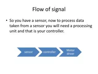
Hardware Description Hardware Description in language such at VHDL or Verilog. Can be behavioral, dataflow, structural, or register-transfer-level. Should be simulated and verified for proper functionality Many functional Open Source hardware designs available under “free” licenses from OpenCores Project.
Synthesis HDL brought into Synthesis tool, BuildGates Extreme. HDL synthesized into a physical hardware description using generic gates. Optimized and mapped to a physical standard cell library. Exported as a gate-level netlist.
Place & Route Netlist imported into Place & Route tool, Silicon Ensemble. Gates are placed as standard cells. Wire routing connects the cells and creates power and ground routes. Exported for use in Cadence Virtuoso
Final Layout Layout can be imported back into Cadence Virtuoso. Can be tested using Design Rule Check and Layout-Versus-Schematic verification. Layout can be integrated with other designs, whether analog, digital, or mixed-signal.
Schematic & Layout Creation • Schematics created and tested to verify functionality • Layouts created to match schematic, checked against process design rules.
Abstract Generation • Abstracts contain only information needed for routing: pin locations, obstructions, etc. • Exported into LEF file for use by P&R tool.
LEF, LIB, ALF Libraries • LEF altered for use in Silicon Ensemble • Verilog gate list created for Silicon Ensemble • Synthesis Libraries created in LIB format, converted to ALF. cell(mux21x1) { area : 342.72 ; vhdl_name : "mux21x1" ; pin(Y) { direction : output; max_fanout : 50; function : "(A*Sel)+(B*Sel')"; } pin(A) { direction : input; fanout_load : 1; } pin(Sel) { direction : input; fanout_load : 1; } pin(B) { direction : input; fanout_load : 1; } }
Standard Cell Rules • Standard sizes so they can adjoin in rows. • Abut to share power/ground rails • Able to be flipped about X or Y axis. • Routing Grid – Pins located at intersections • Defined routing directions for each routing layer.
HVH Routing Directions Metal 1 Layer – Horizontal Routes Metal 2 Layer – Vertical Routes Metal 3 Layer – Horizontal Routes Horizontal Routes Spaced 3.00 microns Vertical Routes Spaced 2.40 microns
Grid Offset Increases number of grid intersections, allowing more places for pins.
OSU_diglib_ami06 • 25 Standard Cells, of which: • 2 Fill Cells • 2 types of D flip-flops • 2 types of Latches • Simple and Compound Gates • Buffers and Tri-State Devices
Library and Flow Test • Compared library against three research cell libraries using AMI 0.5 micron process. • Ran three sample VHDL designs through flow using all four cell libraries.
IIT06_StdCells 26 Cells Illinois Institute of Technology Lacks flip-flop with preset and clear Reference Cell Libraries • UT_LP_AMI06 • 15 Cells • University of Tennessee • Lacks tri-state device • MSU_Jennings • 6 Cells • Mississippi State University • Lacks tri-state device • Has 2 Standard Cell Heights
MiniUART Universal Asynchronous Receiver-Transmitter All standard cell libraries were able to synthesize this design. OpenCores Project Sample Designs • AVR Microprocessor Core • Largest and most complex of sample designs • Requires flip-flop with preset/clear • OpenCores Project • 8-Bit Bidirectional Bus • Simple bus design, requires tri-state device. • Sample from Altera Website
Cell Size Comparison Difference between smallest comparable cell in another cell library and OSU cell.
Post-Synthesis Areas This is the area of the cells used in the design BEFORE placement and routing. OSU library proved to be smallest.
Post-Layout Design Areas The Place-and-Route steps increased the area by a large amount. Bus and MiniUART are 17% and 3% smaller using OSU library. AVR is 54% larger under OSU than other libraries due to dffpc.
Future Work • Add timing and power characterization to OSU_diglib_ami06 library. • Improve dffpc cell to increase over-the-cell routing paths. • Add new cells to library for increased flexibility. • Explore synthesis and place-and-route tools more fully.
Summary & Conclusions • HDL synthesis and place-and-route tool flow developed. • Developed standard cell library to support flow. • Documented library generation steps to easily allow future additions and modifications. • Flow proved successful, and library compared favourably to reference libraries.