Understanding Radio Propagation and Path Loss in Communication Systems
260 likes | 399 Vues
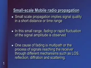
Learn about radio waves, propagation mechanisms, types of waves, antenna gain, path loss, channel capacity, Nyquist Formula, Shannon Capacity Formula, and concepts related to maximizing data rate and efficiency in communication systems.

Understanding Radio Propagation and Path Loss in Communication Systems
E N D
Presentation Transcript
Speed, Wavelength, Frequency Light speed = Wavelength x Frequency = 3 x 10⁸ m/s = 300,000 km/s
Types of Waves Ionosphere (80 - 720 km) Sky wave Mesosphere (50 - 80 km) Stratosphere (12 - 50 km) Space wave Ground wave Troposphere (0 - 12 km) Transmitter Receiver Earth
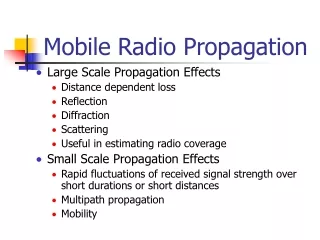
Propagation Mechanisms • Reflection • Propagation wave impinges on an object which is large as compared to wavelength - e.g., the surface of the Earth, buildings, walls, etc. • Diffraction • Radio path between transmitter and receiver obstructed by surface with sharp irregular edges • Waves bend around the obstacle, even when LOS (line of sight) does not exist • Scattering • Objects smaller than the wavelength of the propagation wave - e.g. foliage, street signs, lamp posts
Radio Propagation Effects Building Direct Signal Reflected Signal hb Diffracted Signal hm d Transmitter Receiver
Free-space Propagation hb • The received signal power at distance d: where Pt is transmitting power, Ae is effective area, and Gt is the transmitting antenna gain. Assuming that the radiated power is uniformly distributed over the surface of the sphere. hm Distance d Transmitter Receiver
Antenna Gain • For a circular reflector antenna Gain G = ( D / )2 = net efficiency (depends on the electric field distribution over the antenna aperture, losses, ohmic heating , typically 0.55) D = diameter thus, G = ( D f /c )2, c = f (c is speed of light) Example: • Antenna with diameter = 2 m, frequency = 6 GHz, wavelength = 0.05 m G = 39.4 dB • Frequency = 14 GHz, same diameter, wavelength = 0.021 m G = 46.9 dB * Higher the frequency, higher the gain for the same size antenna
Land Propagation • The received signal power: where Gr is the receiver antenna gain, L is the propagation loss in the channel, i.e., L = LP LS LF Fast fading Slow fading Path loss
Path Loss (Free-space) • Definition of path loss LP : Path Loss in Free-space: where fc is the carrier frequency. This shows greater the fc , more is the loss.
Path Loss (Land Propagation) • Simplest Formula: Lp = A d-α where A and α: propagation constants d : distance between transmitter and receiver α : value of 3 ~ 4 in typical urban area
Channel Capacity • The maximum rate at which data can be transmitted over a given communication channel, under given conditions, is referred to as the channel capacity. • Data rate • The rate in bits per second (bps) at which data can be communicated • Bandwidth • In cycles per second, or Hertz • Constrained by transmitterand the nature of the medium • Error rate • The rate at which errors occur, where an error is the reception of a 1 when a 0 was transmitted or the reception of a 0 when a 1 was transmitted. • We would like to make as efficient use as possible of a given bandwidth, i.e., we would like to get as high a data rate as possible at a particular limit of error rate for a given bandwidth.
Two Formulas • Problem: given a bandwidth, what data rate can we achieve? • Nyquist Formula • Assume noise free • Shannon Capacity Formula • Assume white noise
Nyquist Formula • Assume a channel is noise free. • Nyquist formulation: if the rate of signal transmission is 2B, then a signal with frequencies no greater than B is sufficient to carry the signal rate. • Given bandwidth B, highest signal rate is 2B. • Why is there such a limitation? • due to intersymbol interference, such as is produced by delay distortion. • Given binary signal (two voltage levels), the maximum data rate supported by B Hz is 2B bps. • One signal represents one bit
Nyquist Formula • Signals with more than two levels can be used, i.e., each signal element can represent more than one bit. • E.g., if a signal has 4 different levels, then a signal can be used to represents two bits: 00, 01, 10, 11 • With multilevel signaling, the Nyquist formula becomes: • C= 2B log2M • M is the number of discrete signal levels, B is the given bandwidth, C is the channel capacity in bps. • How large can M be? • The receiver must distinguish one of M possible signal elements. • Noise and other impairments on the transmission line will limit the practical value of M. • Nyquist’s formula indicates that, if all other things are equal, doubling the bandwidth doubles the data rate.
Shannon Capacity Formula • Now consider the relationship among data rate, noise, and error rate. • Faster data rate shortens each bit, so burst of noise affects more bits • At given noise level, higher data rate results in higher error rate • All of these concepts can be tied together neatly in a formula developed by Claude Shannon. • For a given level of noise, we would expect that a greater signal strength would improve the ability to receive data correctly. • The key parameter is the SNR: Signal-to-Noise Ratio, which is the ratio of the power in a signal to the power contained in the noise. • Typically, SNR is measured at receiver, because it is the receiver that processes the signal and recovers the data. • For convenience, this ratio is often reported in decibels • SNR = signal power / noise power • SNRdb=10 log10 (SNR)
Shannon Capacity Formula • Shannon Capacity Formula: • C=B log2(1+SNR) • Only white noise is assumed. Therefore it represents the theoretical maximum that can be achieved. • This is referred to as error-free capacity. • Some remarks: • Given a level of noise, the data rate could be increased by increasing either signal strength or bandwidth. • As the signal strength increases, so do the effects of nonlinearities in the system which leads to an increase in intermodulation noise. • Because noise is assumed to be white, the wider the bandwidth, the more noise is admitted to the system. Thus, as B increases, SNR decreases.
Example • Consider an example that relates the Nyquist and Shannon formulations. Suppose the spectrum of a channel is between 3 MHz and 4 MHz, and SNRdB = 24dB. So, B = 4 MHz – 3 MHz = 1 MHz SNRdB = 24 dB = 10 log10(SNR) SRN = 251 • Using Shannon’s formula, the capacity limit C is: C = 106 x 1og2(1+251) ≈ 8 Mbps. • If we want to achieve this limit, how many signaling levels are required at least? By Nyquist’s formula: C = 2Blog2M We have 8 x 106 = 2 x 10⁶ x log2M M = 16.
KEY POINTS • All of the forms of information can be represented by electromagnetic signals. Depending on the transmission medium and the communications environment, either analog or digital signals can be used to convey information. • Any electromagnetic signals, analog or digital, is made up of a number of constituent frequencies. A key parameter that characterizes the signal is bandwidth, which is the width of the range of frequencies that comprises the signal. In general , the greater the bandwidth of the signal, the greater its information-carrying capacity.
KEY POINTS • A major problem in designing a communications facility is transmission impairment, including attenuation, distortion, and various types of noise. For analog signals, transmission impairments introduce random effects that degrade the quality of the received information and may affect intelligibility. For digital signals, transmission impairments may cause bit errors at the receiver.
KEY POINTS • The designer of a communications facility must deal with four factors: the bandwidth of the signal, the data rate that is used for digital information, the amount of noise and other impairments, and the level of error rate that is acceptable. The bandwidth is limited by the transmission medium and the desire to avoid interference with other nearby signals. Because bandwidth is a scarce resource, we would like to maximize the data rate that is achieved in a given bandwidth. The data rate is limited by the bandwidth, the presence of impairments, and the error rate that is acceptable.