Advanced H4C Series Controller: Hardware Architecture and Functional Capabilities
The H4C Series Controller features innovative hardware architecture designed for control over X, Y, Z, and spindle axes with fast servo response (500 KPPS). Users can rely on a 5.6” TFT LCD for clear display, customizable function keys, and extensive I/O capabilities including standard and serial interfaces. With unique functions like backlash error compensation, macro programming, and real-time diagnostics, this controller enhances automation processes. USB options and programmable coordinates ensure precision in machining tasks.

Advanced H4C Series Controller: Hardware Architecture and Functional Capabilities
E N D
Presentation Transcript
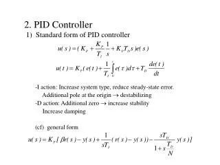
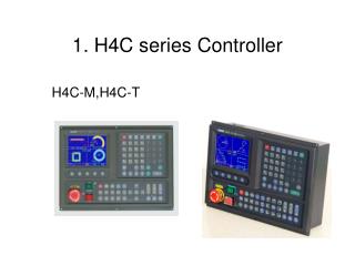
1. H4C series Controller H4C-M,H4C-T
1. Control axis : • X,Y,Z axis( Voltage Command ) + Spindle • X,Y,Z,A axis ( Voltage Command ) + Spindle • 500 KPPS servo response • Spindle : Servo spindle • Invertor + PG card • Invertor without PG card
Axis and MPG Pin assignment • DC +5V only provide for Linear Scale or HandWheel • Plz. Use Isolation Cable if use DC +5V power!
2. Display : • 320x234 16 color 5.6” TFT LCD • 63 Page display ( can be redesigned ) • 5 Function key can be redefined • all of Key can be redefined
3. Input/Output • Standard I/O • 24 Input, 16 Output (H4C,H4C-M, H4C-T )
Serial I/O ( optional ) • 16 Input x 4, 16 Output x 4 (H4C) • 16 Input x 4, 16 Output x 4 (H4C-M,H4C-T)
Serial I/O connect diagram Use DB 15Pin MtoF twisted pair cable(1to1) Each board need DC 24V power
D/A,A/D Pin Assignment Pin 4 : A, Pin 5 : B Pin 9 : A-, Pin 10 : B-
4. RS232 PC communication • BaudRate : 57600, 38400, 19200 • 9600, 4800 • 5. MPG • 6. Program memory : • 512K, Battery Backup • USB disc ( optional ) • Internal PLC 40K
□ Backlash error compensation • □ 40 sets of tool length offset ( H4C-M,H4C-T ) • 08 sets of tool length offset ( H4C ) • □ Self-designed MACRO Program • □ Single block and continuous command • □ Optional Skip function • □ Optional Stop and Feed hold functions
□ Simultaneous use of absolute and incremental programmable coordinates. • □ Self-diagnostic and error signaling function • □ Direct use of “ R”, “ I” and “ J” incremental values for radius in circular cutting • □ MPG hand-wheel test and collision free function for cutting products at the speed controller by MPG
□ Accel./Decel. Mode selectable • linear mode, s-curve mode • □ master-slave mode selectable • □ G65 macro function • □ G,M code can be redefined