Download
1 / 72
770 likes | 1.06k Vues
Chapter 8. Dynamics II : Motion in a Plane. Chapter Goal: To learn how to solve problems about motion in a plane. Slide 8-2. Chapter 8 Preview. Slide 8-3. Chapter 8 Preview. Slide 8-4. Chapter 8 Preview. Slide 8-5. Chapter 8 Preview. Slide 8-6. Chapter 8 Preview. Slide 8-7.

E N D
Chapter 8. Dynamics II: Motion in a Plane Chapter Goal: To learn how to solve problems about motion in a plane. Slide 8-2
Chapter 8 Preview Slide 8-3
Chapter 8 Preview Slide 8-4
Chapter 8 Preview Slide 8-5
Chapter 8 Preview Slide 8-6
Chapter 8 Preview Slide 8-7
Chapter 8 Preview Slide 8-8
Dynamics in Two Dimensions • Suppose the x- and y-components of acceleration are independent of each other. • That is, ax does not depend on y or vy, and ay does not depend on x or vx. • Your problem-solving strategy is to: • Draw a pictorial representation: a motion diagram (if needed) and a free-body diagram. • Use Newton’s second law in component form: The force components (including proper signs) are found from the free-body diagram Slide 8-21
Dynamics in Two Dimensions Dynamics in Two Dimensions • Solve for the acceleration. If the acceleration is constant, use the two-dimensional kinematic equations of Chapter 4 to find velocities and positions: Slide 8-22
Example 8.1 Rocketing in the Wind Slide 8-23
Example 8.1 Rocketing in the Wind Slide 8-24
Example 8.1 Rocketing in the Wind Slide 8-25
Example 8.1 Rocketing in the Wind Slide 8-26
Example 8.1 Rocketing in the Wind Slide 8-27
Example 8.1 Rocketing in the Wind Slide 8-28
Example 8.1 Rocketing in the Wind Slide 8-29
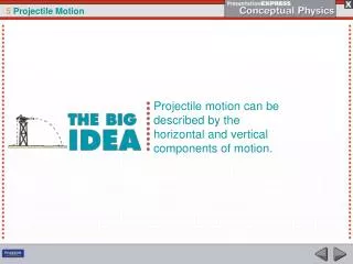
Projectile Motion: Review • In the absence of air resistance, a projectile moves under the influence of only gravity. • If we choose a coordinate system with a vertical y-axis, then • Consequently, from Newton’s second law, the acceleration is Slide 8-30
Projectile Motion: Review • Consider a projectile with initial speed v0, and a launch angle of above the horizontal. • In Chapter 4 (eq 4.16) we found that the distance it travels before it returns to the same elevation from which it was launched (the range) is: Trajectories of a projectile launched at different angles with a speed of 99 m/s. • The maximum range occurs for 45. • All of these results neglect the effect of air resistance. Slide 8-31
Projectile Motion • For low-mass projectiles on earth, the effects of air resistance, or drag, are too large to ignore. • When drag is included, the angle for maximum range of a projectile depends both on its size and mass. • The optimum angle is roughly 35 for baseballs. • The flight of a golf ball is even more complex, because of the dimples and effects of spin. • Professional golfers achieve their maximum range at launch angles of barely 15! Slide 8-32
Projectile Motion • The acceleration of a typical projectile subject to drag force from the air is: • The components of acceleration are not independent of each other. • These equations can only be solved numerically. • The figure shows the numerical solution for a 5-g plastic ball. Slide 8-33
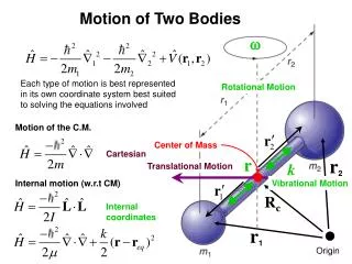
Uniform Circular Motion • When describing circular motion, it is convenient to define a moving rtz-coordinate system. • The origin moves along with a certain particle moving in a circular path. • The r-axis (radial) points from the particle toward the center of the circle. • The t-axis (tangential) is tangent to the circle, pointing in the ccw direction. • The z-axis is perpendicular to the plane of motion. Slide 8-34
Uniform Circular Motion • A particle in uniform circular motion with angular velocity ω has velocity v =ωr, in the tangential direction. • The acceleration of uniform circular motion points to the center of the circle. • The rtz-components of and are: Slide 8-35
QuickCheck 8.1 The diagram shows three points of a motion diagram. The particle changes direction with no change of speed. What is the acceleration at point 2? Slide 8-36
QuickCheck 8.1 The diagram shows three points of a motion diagram. The particle changes direction with no change of speed. What is the acceleration at point 2? Acceleration of changing direction Slide 8-37
QuickCheck 8.2 A toy car moves around a circular track at constant speed. It suddenly doubles its speed — a change of a factor of 2. As a result, the centripetal acceleration changes by a factor of 1/4. 1/2. No change since the radius doesn’t change. 2. 4. Slide 8-38
QuickCheck 8.2 A toy car moves around a circular track at constant speed. It suddenly doubles its speed—a change of a factor of 2. As a result, the centripetal acceleration changes by a factor of 1/4. 1/2. No change since the radius doesn’t change. 2. 4. Slide 8-39
Example 8.2 The Ultracentrifuge Slide 8-40
Example 8.2 The Ultracentrifuge Slide 8-41
Dynamics of Uniform Circular Motion • An object in uniform circular motion is not traveling at a constant velocity in a straight line. • Consequently, the particle must have a net force acting on it • Without such a force, the object would move off in a straight line tangent to the circle. • The car would end up in the ditch! Highway and racetrack curves are banked to allow the normal force of the road to provide the centripetal acceleration of the turn. Slide 8-42
Dynamics of Uniform Circular Motion • The figure shows a particle in uniform circular motion. • The net force must point in the radial direction, toward the center of the circle. • This centripetal force is not a new force; it must be provided by familiar forces. Slide 8-43
QuickCheck 8.3 An ice hockey puck is tied by a string to a stake in the ice. The puck is then swung in a circle. What force or forces does the puck feel? A new force: the centripetal force. A new force: the centrifugal force. One or more of our familiar forces pushing outward. One or more of our familiar forces pulling inward. I have no clue. Slide 8-44
QuickCheck 8.3 An ice hockey puck is tied by a string to a stake in the ice. The puck is then swung in a circle. What force or forces does the puck feel? A new force: the centripetal force. A new force: the centrifugal force. One or more of our familiar forces pushing outward. One or more of our familiar forces pulling inward. I have no clue. The rules about what is or is not a force haven’t changed. Force must be exerted at a point of contact (except for gravity). Force must have an identifiable agent doing the pushing or pulling. The net force must point in the direction of acceleration (Newton’s second law). Slide 8-45
QuickCheck 8.4 • An ice hockey puck is tied by a string to a stake in the ice. The puck is then swung in a circle. What force is producing the centripetal acceleration of the puck? • Gravity • Air resistance • Friction • Normal force • Tension in the string Slide 8-46
QuickCheck 8.4 • An ice hockey puck is tied by a string to a stake in the ice. The puck is then swung in a circle. What force is producing the centripetal acceleration of the puck? • Gravity • Air resistance • Friction • Normal force • Tension in the string Slide 8-47
Example 8.4 Turning the Corner I Slide 8-48
Example 8.4 Turning the Corner I • VISUALIZE • The second figure below shows the top view of a tire as it turns a corner. • The force that prevents the tire from sliding across a surface is static friction. • Static friction pushes sideways on the tire, perpendicular to the velocity, since the car is not speeding up or slowing down. • The free-body diagram, drawn from behind the car, shows the static friction pointing toward the center of the circle. Slide 8-49
Example 8.4 Turning the Corner I Slide 8-50
Example 8.4 Turning the Corner I Slide 8-51
Example 8.4 Turning the Corner I Slide 8-52
Banked Curves • Real highway curves are banked by being tilted up at the outside edge of the curve. • The radial component of the normal force can provide centripetal acceleration needed to turn the car. (Ex 8.5) • For a curve of radius r banked at an angle , the exact speed at which a car must take the curve without assistance from friction is . Slide 8-53
Banked Curves • Consider a car going around a banked curve at a speed higher than . • In this case, static friction must prevent the car from slipping up the hill. Slide 8-54
Banked Curves • Consider a car going around a banked curve at a speed slower than . • In this case, static friction must prevent the car from slipping down the hill. Slide 8-55
Circular Orbits • The figure shows a perfectly smooth, spherical, airless planet with one tower of height h. • A projectile is launched parallel to the ground with speed v0 . • If v0 is very small, as in trajectory A, it simply falls to the ground along a parabolic trajectory. • This is the “flat-earth approximation.” Slide 8-58
Circular Orbits • As the initial speed v0 is increased, the range of the projectile increases as the ground curves away from it. • Trajectories B and C are of this type. • If v0 is sufficiently large, there comes a point where the trajectory and the curve of the earth are parallel. • In this case, the projectile “falls” but it never gets any closer to the ground! • This is trajectory D, called an orbit. Slide 8-59
Circular Orbits • In the flat-earth approximation, shown in figure (a), the gravitational force on an object of mass m is: • Since actual planets are spherical, the real force of gravity is toward the center of the planet, as shown in figure (b). Slide 8-60
Circular Orbits • An object in a low circular orbit has acceleration: • If the object moves in a circle of radius r at speed vorbit the centripetal acceleration is: • The required speed for a circular orbit near a planet’s surface, neglecting air resistance, is: Slide 8-61
Circular Orbits • The period of a low-earth-orbit satellite is: • If r is approximately the radius of the earth Re =6400km, then T is about 90 minutes. • An orbiting spacecraft is constantly in free fall, falling under the influence only of the gravitational force. • This is why astronauts feel weightless in space. Slide 8-62
Fictitious Forces • If you are riding in a car that makes a sudden stop, you seem to be hurled forward. • You can describe your experience in terms of fictitious forces. • Fictitious forces are not real because no agent is exerting them. • Fictitious forces describe your motion relative to a noninertial reference frame. Slide 8-64
Centrifugal Force? • The figure shows a bird’s-eye view of you riding in a car as it makes a left turn. • From the perspective of an inertial reference frame, the normal force from the door points inward, keeping you on the road with the car. • Relative to the noninertial reference frame of the car, you feel pushed toward the outside of the curve. • The fictitious force which seems to push an object to the outside of a circle is called the centrifugal force. • There really is no such force in an inertial reference frame. Slide 8-65
QuickCheck 8.6 A coin sits on a turntable as the table steadily rotates ccw. The free-body diagrams below show the coin from behind, moving away from you. Which is the correct diagram? Slide 8-66