Download
1 / 34
390 likes | 674 Vues
Basic Logic Operations and Standard Logic Gates [Lecture:1] Instructor: Sajib Roy Lecturer, ETE, ULAB. ETE 204 – Digital Electronics. What is an analog signal?. Analog Signal. An analog signal is a signal that can take on a continuous range of values. Analog Signal.

E N D
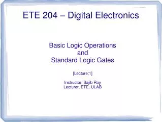
Basic Logic Operations and Standard Logic Gates [Lecture:1] Instructor: Sajib Roy Lecturer, ETE, ULAB ETE 204 – Digital Electronics
ETE 204 - Digital Electronics What is an analog signal?
ETE 204 - Digital Electronics Analog Signal • An analog signal is a signal that can take on a continuous range of values.
ETE 204 - Digital Electronics Analog Signal • Most, if not all, physical (naturally occurring) quantities are analog values. • Time • Temperature • Pressure
ETE 204 - Digital Electronics What is an digital signal?
ETE 204 - Digital Electronics Digital Signal • An digital signal is a signal that can take on only discrete (specific) values.
ETE 204 - Digital Electronics What is an binary signal?
ETE 204 - Digital Electronics Binary Signal • An binary signal is a signal that can take on only two values. • Typically represented by 0 and 1.
ETE 204 - Digital Electronics Can a binary number be used to represent an analog value? What about accuracy (or is it precision)?
ETE 204 - Digital Electronics Can a binary number be used to represent an digital value? How many bits are required?
ETE 204 - Digital Electronics Sample and Hold ADC Binary Encoder analog sampled digital binary Processing Physical Quantities • The analog signal (representing the physical quantity) must be sampled at specific instances in time. • The sampled values must be digitized. • The digital value must be encoded in binary.
ETE 204 - Digital Electronics Basic Logic Operations
Definition: the output is true (1) if both inputs are true (1). ETE 204 - Digital Electronics AND logical operator F = A.B = AB = “A and B” Boolean expression F Truth table Symbol (aka. logic gate)
Definition: the output is true (1) if either or both inputs are true (1). ETE 204 - Digital Electronics F F OR logical operator F = A+B = “A or B” Boolean expression Truth table Symbol
Definition: the output is true (1) if the input is false (0). ETE 204 - Digital Electronics NOT logical operator F = A' = “ not A” Boolean expression Truth table A F = A' Symbol
ETE 204 - Digital Electronics Order of Precedence • The order of precedence of the basic logic operations is defined as follows: • NOT • AND • OR • The order of precedence can be modified by using parenthesis.
ETE 204 - Digital Electronics Functionally Complete • The AND, OR, and NOT operations comprise a functionally complete set. • All logic functions can be expressed in terms of these logic operations. • All logic circuits can be realized using the associated logic gates.
Definition: the output is false (0) iff both inputs are true (1). ETE 204 - Digital Electronics NAND F = (A.B)' = “not (A and B)” Boolean expression F = (A.B)' Truth table Symbol shorthand for inversion
Definition: the output is false (0) if either or both inputs are true (1). ETE 204 - Digital Electronics F F NOR F = (A+B)' = “not (A or B)” Boolean expression F = (A+B)' F Truth table Symbol shorthand for inversion
Definition: the output is true (1) if either but not both inputs are true (1). ETE 204 - Digital Electronics XOR F = A xor B Boolean expression logical operator Truth table Symbol
Definition: the output is false (0) if either but not both inputs are true (1). ETE 204 - Digital Electronics XNOR (aka. Equivalence) F = A xnor B Boolean expression logical operator Symbol Truth table
ETE 204 - Digital Electronics Logic Circuits • Logic circuits are realized through the interconnection of logic gates. • Each logic gate represents a logical operation. • This can be done using • discrete components • Standard Logic Gates • programmable devices • Read-only Memories (ROM) • Programmable Logic Devices (PLD) • Field Programmable Gate Arrays (FPGA)
ETE 204 - Digital Electronics Standard Logic Gates
ETE 204 - Digital Electronics Standard Logic Gates Note: “xx” refers to the logic family
ETE 204 - Digital Electronics Standard Logic Gates • Data sheets provide essential information: • Logic Function • Truth Table • Pin-out • Electrical Characteristics • Timing Characteristics • Package Description(s) • This information is necessary when building logic circuits from discrete components. • Each logic family has a unique set of characteristics.
ECE 301 - Digital Electronics Standard Logic Gates: 74xx08 pin-out Truth table ETE 204 - Digital Electronics
ECE 301 - Digital Electronics Standard Logic Gates: 74xx32 pin-out Truth table ETE 204 - Digital Electronics
ECE 301 - Digital Electronics Standard Logic Gates: 74xx04 pin-out Truth table ETE 204 - Digital Electronics
ETE 204 - Digital Electronics C B inputs output F A Building a Logic Circuit Circuit Diagram 74xx08 74xx04 74xx32 74xx08 Boolean Expression F = B'.C + A.B
ETE 204 - Digital Electronics V DD 7404 7408 7432 A B C F Building a Logic Circuit Wiring Diagram components wires inputs output
Draw the circuit diagram and wiring diagram for the following Boolean expression: F = A'.B + A.B' Example ETE 204 - Digital Electronics
ETE 204 - Digital Electronics Example (circuit diagram)
ETE 204 - Digital Electronics Example
ETE 204 - Digital Electronics Questions?