CHAPTER 6: MECHANICAL PROPERTIES
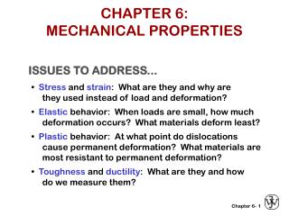
CHAPTER 6: MECHANICAL PROPERTIES. ISSUES TO ADDRESS. • Stress and strain : What are they and why are they used instead of load and deformation?. • Elastic behavior: When loads are small, how much deformation occurs? What materials deform least?.

CHAPTER 6: MECHANICAL PROPERTIES
E N D
Presentation Transcript
CHAPTER 6: MECHANICAL PROPERTIES ISSUES TO ADDRESS... • Stress and strain: What are they and why are they used instead of load and deformation? • Elastic behavior: When loads are small, how much deformation occurs? What materials deform least? • Plastic behavior: At what point do dislocations cause permanent deformation? What materials are most resistant to permanent deformation? • Toughness and ductility: What are they and how do we measure them? 1
INTRODUCTION (I) • The need for • standardized language for expressing mechanical properties of materials: • STRENGTH, HARDNESS, DUCTILITY, and STIFFNESS • standardized test methods: • American Society for Testing and Materials Standards and others…
INTRODUCTION (II) The result of mechanical testing is generally a response curve or a (set of) number(s), in this case a STRESS vs. STRAIN curve Courtesy of Plastics Technology Laboratories, Inc 50 Pearl Street, Pittsfield, MA 01201
Basic Concepts of Stress and Strain • Need to compare load on specimens of various size and shapes: • For tension and compression • Engineering Stress, σ = F / A0 , where F is load applied perpendicular to speciment crosssection and A0 is cross-sectional area (perpendicular tothe force) before application of the load. • Engineering Strain, ε = Δl / l0 ( x 100 %), where Δlchange in length, lo is the original length. • These definitions of stress and strain allow one tocompare test results for specimens of different cross-sectionalarea A0 and of different length l0.
Basic Concepts of Stress and Strain • Need to compare load on specimens of various size and shapes: • For tension and compression • Engineering Stress, σ = F / A0 , where F is load applied perpendicular to speciment crosssection and A0 is cross-sectional area (perpendicular tothe force) before application of the load. • Engineering Strain, ε = Δl / l0 ( x 100 %), where Δlchange in length, lo is the original length. • For shear • Shear Stress, τ = F / A0 , where F is load applied parallel to upper and lower specimen faces of area A0. • Shear Strain, γ = tan θ ( x 100 %), where θ is the strain angle. These definitions of stress and strain allow one tocompare test results for specimens of different crosssectionalarea A0 and of different length l0.
ENGINEERING STRESS • Tensile stress, s: • Shear stress, t: Stress has units: N/m2 or lb/in2 4
ENGINEERING STRAIN • Tensile strain: • Lateral strain: Applied Resulting • Shear strain: Strain is always dimensionless. 8
COMMON STATES OF STRESS F F A = cross sectional o Area (when unloaded) • Simple tension: cable Note: σ > 0 here ! Ski lift(photo courtesy P.M. Anderson) • Simple shear: drive shaft Note: t = M/AcR here. 5
OTHER COMMON STRESS STATES (1) • Simple compression: A o (photo courtesy P.M. Anderson) Note: compressive structure member (s < 0 here). Balanced Rock, Arches National Park (photo courtesy P.M. Anderson) 6
OTHER COMMON STRESS STATES (2) • Bi-axial tension: • Hydrostatic compression: Pressurized tank (photo courtesy P.M. Anderson) (photo courtesy P.M. Anderson) s< 0 h 7
OTHER COMMON STRESS STATES (3) • State of stresses in college life: σ2, family σ1, classes s< 0 h σ3, friends, etc… σ4, daily challenges, etc… 7
SIMPLE STRESS-STRAIN TESTING Typical tensile test machine Typical tensile specimen Adapted from Fig. 6.2, Callister 6e. gauge (portion of sample with = length reduced cross section) Adapted from Fig. 6.3, Callister 6e. (Fig. 6.3 is taken from H.W. Hayden, W.G. Moffatt, and J. Wulff, The Structure and Properties of Materials, Vol. III, Mechanical Behavior, p. 2, John Wiley and Sons, New York, 1965.) • Other types of tests: • compression: brittle materials (e.g., concrete) • torsion: cylindrical tubes, shafts. • hardness: surfaces of metals, ceramics 9
• Typical tensile specimen Adapted from Fig. 6.2, Callister 7e. specimen extensometer gauge length Stress-Strain Testing • Typical tensile test machine Adapted from Fig. 6.3, Callister 7e. (Fig. 6.3 is taken from H.W. Hayden, W.G. Moffatt, and J. Wulff, The Structure and Properties of Materials, Vol. III, Mechanical Behavior, p. 2, John Wiley and Sons, New York, 1965.)
How does deformation take place in the material at an atomic scale ? • Two types of deformation : • Elastic • Reversible, no change in the shape and the size of the specimen when the load is released ! • When under load volume of the material changes ! • Plastic • Irreversible, dislocations cause slip, bonds are broken, new bonds are made. • When load is released, specimen does not return to original size and shape, but volume is preserved !
STRESS-STRAIN CURVE Necking starts STRESS σUTS REGION I REGION III REGION II HARDENING OCCURS DISLOCATION MOTION AND GENERATION ! σYIELD l0 + le σFAILURE or σFRACTURE Region I : Elastic Deformation Hooke’s Law Region II: Uniform Plastic Deformation Strain is uniform across material Region III: Non-uniform Plastic Deformation Deformation is limited to “neck” region E l0 + le + lp STRAIN εUTS εYIELD l0
ELASTIC DEFORMATION 1. Initial 2. Small load 3. Unload Elastic means reversible! Bonds stretch and but recover when load is released. 2
LINEAR ELASTIC PROPERTIES • Modulus of Elasticity, E: (also known as Young's modulus) F e Under Load • Hooke's Law (Linear): s = Ee • Poisson's ratio, n: metals: n ~ 0.33 ceramics: ~0.25 polymers: ~0.40 e L e L No load e F n - simple 1 tension test Units: E: [GPa] or [psi] n: dimensionless 10
NON-LINEAR ELASTIC PROPERTIES • Some materials will exhibit a non-linear elastic behavior under stress ! Examples are polymers, gray cast iron, concrete, etc…
Linear Elastic Deformation (Atomic Scale) Chapter 2: Inter-atomic Bonding ! Young’s Modulus α (dF/dr) at ro , what else ? If we increase temperature, how will E behave ?
YOUNG’S MODULI: COMPARISON Graphite Ceramics Semicond Metals Alloys Composites /fibers Polymers E(GPa) Based on data in Table B2, Callister 6e. Composite data based on reinforced epoxy with 60 vol% of aligned carbon (CFRE), aramid (AFRE), or glass (GFRE) fibers. 12
PLASTIC DEFORMATION (METALS) 1. Initial 2. Small load 3. Unload Plastic means permanent! 3
PLASTIC (PERMANENT) DEFORMATION (at lower temperatures, T < Tmelt/3) • Simple tension test: 14
YIELD STRENGTH, sy Some materials do NOT exhibit a distinct transition from elastic to plastic region under stress, so by convention a straight line is drawn parallel to the stress strain curve with 0.2 % strain. The stress at the intersection is called the yield stress !
HARDENING • An increase in sy due to plastic deformation. • Curve fit to the stress-strain response: 22
YIELD STRENGTH: COMPARISON Room T values Based on data in Table B4, Callister 6e. a = annealed hr = hot rolled ag = aged cd = cold drawn cw = cold worked qt = quenched & tempered 16
TENSILE STRENGTH, TS • Maximum possible engineering stress in tension. NECKING Adapted from Fig. 6.11, Callister 6e. FRACTURE • Metals: occurs when noticeable necking starts. • Ceramics: occurs when crack propagation starts. • Polymers: occurs when polymer backbones are aligned and about to break. 17
TENSILE STRENGTH: COMPARISON Room T values Based on data in Table B4, Callister 6e. a = annealed hr = hot rolled ag = aged cd = cold drawn cw = cold worked qt = quenched & tempered AFRE, GFRE, & CFRE = aramid, glass, & carbon fiber-reinforced epoxy composites, with 60 vol% fibers. 18
DUCTILITY, %EL • Plastic tensile strain at failure: Adapted from Fig. 6.13, Callister 6e. • Note: %AR and %EL are often comparable. --Reason: crystal slip does not change material volume. --%AR > %EL possible if internal voids form in neck. 19
Mechanical Strength of Materials Yield Strength, Tensile Strength and Ductility can be improved by alloying, heat and mechanical treatment, but Youngs Modulus is rather insensitive to such processing ! Temperature effects : YS, TS and YM decrease with increasing temperature, but ductility increases with temperature !
TOUGHNESS & RESILIENCE • Energy to break a unit volume of material • Approximate by the area under the stress-strain curve. RESILIENCE is energy stored in the material w/o plastic deformation ! Ur = σy2 / 2 E TOUGHNESS is total energy stored in the material upon fracture ! 20
1 @ s e U r y y 2 Resilience, Ur • Ability of a material to store energy • Energy stored best in elastic region If we assume a linear stress-strain curve this simplifies to Adapted from Fig. 6.15, Callister 7e.
TRUE STRESS & STRAIN σT = σ (1+ ε ) εT = ln (1+ε) The material does NOT get weaker past M
HARDNESS • Resistance to permanently indenting the surface. • Large hardness means: --resistance to plastic deformation or cracking in compression. --better wear properties. Adapted from Fig. 6.18, Callister 6e. (Fig. 6.18 is adapted from G.F. Kinney, Engineering Properties and Applications of Plastics, p. 202, John Wiley and Sons, 1957.) 21
Hardness: Measurement • Rockwell • No major sample damage • Each scale runs to 130 but only useful in range 20-100. • Minor load 10 kg • Major load 60 (A), 100 (B) & 150 (C) kg • A = diamond, B = 1/16 in. ball, C = diamond • HB = Brinell Hardness • TS (psia) = 500 x HB • TS (MPa) = 3.45 x HB
Hardness: Measurement Table 6.5
HARDNESS !! • Relatively simple and cheap technique • Non-destructive • Related to many other mechanical properties
Variability in Material Properties • Elastic modulus is material property • Critical properties depend largely on sample flaws (defects, etc.). Large sample to sample variability. • Statistics • Mean • Standard Deviation where n is the number of data points
Design or Safety Factors d 1045 plain carbon steel: L o s = 310 MPa y 5 TS = 565 MPa F = 220,000N • Design uncertainties mean we do not push the limit. • Factor of safety, N Often N is between 1.2 and 4 • Example: Calculate a diameter, d, to ensure that yield does not occur in the 1045 carbon steel rod below. Use a factor of safety of 5. d = 0.067 m = 6.7 cm
SUMMARY • Stress and strain: These are size-independent measures of load and displacement, respectively. • Elastic behavior: This reversible behavior often shows a linear relation between stress and strain. To minimize deformation, select a material with a large elastic modulus (E or G). • Plastic behavior: This permanent deformation behavior occurs when the tensile (or compressive) uniaxial stress reaches sy. • Toughness: The energy needed to break a unit volume of material. • Ductility: The plastic strain at failure. Note: For materials selection cases related to mechanical behavior, see slides 22-4 to 22-10. 24
ANNOUNCEMENTS Reading: Chapter 6 and Chapter 7 Homework : Example problems: 6.1, 6.2, 6.3 Due date: 27-04-2011 0