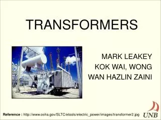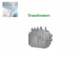
Chapter 2 Transformers
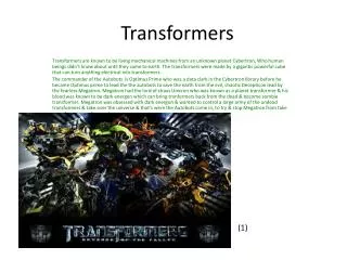
Chapter 2 Transformers. What is a transformer ?. • It is an electrical device that transfers electrical power from one circuit to another by magnetic coupling It does so without change of frequency and without any moving parts. Transformer works only with AC. Because transformers

Chapter 2 Transformers
E N D
Presentation Transcript
Chapter 2 Transformers
What is a transformer ? •It is an electrical device that transfers electrical power from one circuit to another by magnetic coupling It does so without change of frequency and without any moving parts. Transformer works only with AC
Because transformers • adjust the voltage coming into the appliance to keep it operating properly • measure high voltages and currents in a safe manner. •help using devices in wet areas. Why do we need transformers?
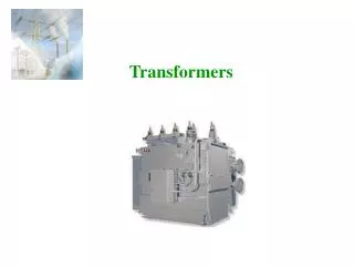
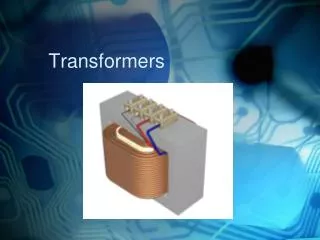
Construction of Transformer : The transformer is very simple in construction It consists of magnetic circuit linking with two windings.
Construction of Transformer : Core is made up of laminations to reduce the eddy current lossesThe thickness of laminations is usually 0.4mm
Construction of Transformer The coil windings are wound on the limbs and are insulated from each other
Principle of operation 1. When current in the primary coil changes being alternating in nature, a changing magnetic field is produced 2. This changing magnetic field gets associated with the secondary through the soft iron core 3. Hence magnetic flux linked with the secondary coil changes. 4. Which induces e.m.f. in the secondary.
Principle of operation The rms value of the induced voltages are
Principle of operation For ideal transformer E1=V1 and E2= V2 The power in ideal transformer Then
Transformer doesn't work on a DC supply According to the principle of Transformer operation It doesn't work on a DC supply since the rate of change of flux is zero
Transformer Rating It is written in terms of Apparent Power. Apparent power is the product of its rated current and rated voltage. • Where, • I1 and I2 = rated current on primary and secondary winding. • V1 and V2 = rated voltage on primary and secondary winding. • Rated currents are the full load currents in transformer
Transformer Rating and Name Plate Assume that the transformer has the following name plate ratings: 40 kVA, 11 kV/ 440 V, 50 Hz What do these numbers imply?
Classification of transformers: • according to turns ratio: • 1- step up transformer • 2- step down transformer
Classification of transformers: • according to number of phases • 1- single phase transformer • 2- poly phase transformer
Classification of transformers: • according to their function : • 1- power transformer • 2- distribution transformer • 3- measuring transformers • A)voltage transformer • B) current transformer • 4-Autotransformer- Tapped autotransformer
1-Power Transformer: • It is a power transformer connected to the output of a generator and used to step its voltage up to the transmission level .
2-Distribution transformer • It is a transformer converting the distribution voltage down to the final level
3- measuring transformers A)Voltage Transformer
3- measuring transformers B)Current Transformer
According to cooling • A)Air Cooling For Dry Type Transformers: • It is used for transformers that use voltages below 25KV • 1)Air natural Type (A.N.) • This type of Transformer Cooling method applies to dry type transformer of small rating. • As power ratings increase, transformers are often cooled by forced-air cooling
According to cooling • 2)Air Forced type (A.F.) • The air is forced on to the tank surface to increase the rate of heat dissipation. • The fans are switched on when the temperature of the winding increases above permissible level.
According to cooling • B)Cooling For Oil Immersed Transformers: • 1)Oil Natural Air Natural Type (O.N.A.N.) • This type of Transformer cooling is widely used for oil filled transformers up to about 30MVA. • Heat is transferred from transformer windings and core to the oil and • the heated oil is cooled by the natural air. • Cooling area is increased by providing the cooling tubes.
According to cooling • B)Cooling For Oil Immersed Transformers: Oil Natural Air Natural Transformer Cooling
According to cooling • B)Cooling For Oil Immersed Transformers: • 2)Oil Natural Air Forced Type (O.N.A.F.) • •In higher rating transformers where the heat dissipation is difficult • • this type of cooling is used. • • Fans are used to forced and air blast on radiators.
According to cooling • B)Cooling For Oil Immersed Transformers: Oil Natural Air Forced Transformer Cooling
According to cooling • B)Cooling For Oil Immersed Transformers: 3)Oil Forced Air Forced Type (O.F.A.F.) Oil Natural Air Forced type of cooling is not adequate to remove the heat caused by the losses. Transformers above 60 MVA employ a combination of Forced Oil and Forced Air Cooling.
According to cooling • B)Cooling For Oil Immersed Transformers: Oil Forced Air Forced Transformer Cooling
According to cooling • B)Cooling For Oil Immersed Transformers: 4)Oil Forced Water Forced (O.F.W.F.) This type of cooling Is provided for very large transformers which have ratings of some hundreds of MVA This type of transformers is used in large substations and power plants.
According to cooling • B)Cooling For Oil Immersed Transformers: Oil Forced Water Forced Transformer Cooling
Transformer Equivalent Circuit The equivalent circuit shown can be used to predict the performance of the transformer
Determination of Equivalent Circuit Parameters • All the circuit parameters can be easily determined by performing three tests, • D.C. test • a no-load test (or open circuit test) • short circuit test
1-D.C. test • This test is carried out to measure the resistance of each winding • The resistance of each winding is obtained from the Ohms Law R = E/i
2-Open circuit (no load) test • Open circuit test is carried out to determine magnetizing current and core losses • This test is performed by applying • the rated voltage to LV winding • keeping the HV winding open
2-Open circuit (no load) test The wattmeter reading gives the full load core losses since the no load test is carried at full load
3-Short circuit (SC) test • In this test the secondary terminals are short- circuited through an ammeter • The primary terminals are connected to a low-voltage source • The input voltage is adjusted until the current in the short circuited windings is equal to its rated value
3-Short circuit test The wattmeter reading gives the full load copper losses since the core losses is very small at this reduced voltage
Voltage Regulation It is defined as the variation of no-load to full-load voltage of either the primary or secondary as percentage of no-load voltage The purpose of voltage regulation is to determine the percentage of voltage drop between no load and full load.
Transformer Efficiency Transformer efficiency is defined as
Types of losses incurred in a transformer: • 1- Copper I2R losses • 2- Core losses (hysteresis losses and eddy current losses) Transformer Losses and Efficiency
Transformer Losses and Efficiency Transformer efficiency may be calculated using the following: Ideal transformer will have maximum efficiency at a load such that copper losses = iron losses
Example The open-circuit and short-circuit tests conducted on 50 KVA transformer gave the following result: Calculate (a) efficiency at full load and 0.8 power factor (b) the voltage regulation if full loadprimary voltage is 3200V
Solution From open-circuit test Core losses=460 W From short-circuit test Copper losses= 540W (a)efficiency at full load and 0.8 power factor