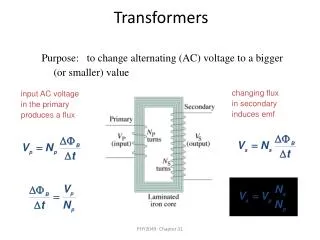
Transformers
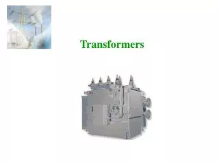
Transformers. Transformer. An A.C. device used to change high voltage low current A.C. into low voltage high current A.C. and vice-versa without changing the frequency In brief, 1. Transfers electric power from one circuit to another 2. It does so without a change of frequency


Transformers
E N D
Presentation Transcript
Transformer An A.C. device used to change high voltage low current A.C. into low voltage high current A.C. and vice-versa without changing the frequency In brief, 1. Transfers electric power from one circuit to another 2. It does so without a change of frequency 3. It accomplishes this by electromagnetic induction 4. Where the two electric circuits are in mutual inductive influence of each other.
Principle of operation It is based on principle of MUTUAL INDUCTION. According to which an e.m.f. is induced in a coil when current in the neighbouring coil changes.
Constructional detail : Shell type • Windings are wrapped around the center leg of a laminated core.
Core type • Windings are wrapped around two sides of a laminated square core.
Sectional view of transformers Note: High voltage conductors are smaller cross section conductors than the low voltage coils
Core type Fig1: Coil and laminations of core type transformer Fig2: Various types of cores
Shell type • The HV and LV windings are split into no. of sections • Where HV winding lies between two LV windings • In sandwich coils leakage can be controlled Fig: Sandwich windings
Working of a transformer 1. When current in the primary coil changes being alternating in nature, a changing magnetic field is produced 2. This changing magnetic field gets associated with the secondary through the soft iron core 3. Hence magnetic flux linked with the secondary coil changes. 4. Which induces e.m.f. in the secondary.
Ideal Transformers • Zero leakage flux: -Fluxes produced by the primary and secondary currents are confined within the core • The windings have no resistance: - Induced voltages equal applied voltages • The core has infinite permeability - Reluctance of the core is zero - Negligible current is required to establish magnetic flux • Loss-less magnetic core - No hysteresis or eddy currents
Ideal transformer V1 – supply voltage ; I1- noload input current ; V2- output voltgae; I2- output current Im- magnetising current; E1-self induced emf ; E2- mutually induced emf
EMF equation of a transformer • Worked out on board / • Refer pdf file: emf-equation-of-tranformer
Transformer on load assuming no voltage drop in the winding • Fig shows the Phasor diagram of a transformer on load by assuming • No voltage drop in the winding • Equal no. of primary and secondary turns
Transformer on load Fig. a: Ideal transformer on load Fig. b: Main flux and leakage flux in a transformer
Equivalent circuit of a transformer No load equivalent circuit:
Equivalent circuit parameters referred to primary and secondary sides respectively
Contd., • The effect of circuit parameters shouldn’t be changed while transferring the parameters from one side to another side • It can be proved that a resistance of R2 in sec. is equivalent to R2/k2will be denoted as R2’(ie. Equivalent sec. resistance w.r.t primary) which would have caused the same loss as R2 in secondary,
Equivalent circuit referred to secondary side • Transferring primary side parameters to secondary side Similarly exciting circuit parameters are also transferred to secondary as Ro’ and Xo’
Approximate equivalent circuit • Since the noload current is 1% of the full load current, the nolad circuit can be neglected
Transformer Tests • The performance of a transformer can be calculated on the basis of equivalent circuit • The four main parameters of equivalent circuit are: • - R01 as referred to primary (or secondary R02) • - the equivalent leakage reactance X01as referred to primary (or secondary X02) • - Magnetising susceptance B0 ( or reactance X0) • - core loss conductance G0 (or resistance R0) • The above constants can be easily determined by two tests • - Oper circuit test (O.C test / No load test) • - Short circuit test (S.C test/Impedance test) • These tests are economical and convenient • - these tests furnish the result without actually loading the transformer Electrical Machines
Open-circuit Test In Open Circuit Test the transformer’s secondary winding is open-circuited, and its primary winding is connected to a full-rated line voltage. • Usually conducted on H.V side • To find (i) No load loss or core loss (ii) No load current Io which is helpful in finding Go(or Ro ) and Bo (or Xo )
Short-circuit Test In Short Circuit Test the secondary terminals are short circuited, and the primary terminals are connected to a fairly low-voltage source The input voltage is adjusted until the current in the short circuited windings is equal to its rated value. The input voltage, current and power is measured. • Usually conducted on L.V side • To find (i) Full load copper loss – to pre determine the efficiency (ii) Z01 or Z02; X01 or X02; R01 or R02 - to predetermine the voltage regulation
Transformer Voltage Regulation and Efficiency The output voltage of a transformer varies with the load even if the input voltage remains constant. This is because a real transformer has series impedance within it. Full load Voltage Regulation is a quantity that compares the output voltage at no load with the output voltage at full load, defined by this equation: Ideal transformer, VR = 0%. Electrical Machines
Voltage regulation of a transformer recall Secondary voltage on no-load V2 is a secondary terminal voltage on full load Substitute we have
Transformer Phasor Diagram To determine the voltage regulation of a transformer, it is necessary understand the voltage drops within it. Electrical Machines Aamir Hasan Khan
Transformer Phasor Diagram Ignoring the excitation of the branch (since the current flow through the branch is considered to be small), more consideration is given to the series impedances (Req +jXeq). Voltage Regulation depends on magnitude of the series impedance and the phase angle of the current flowing through the transformer. Phasor diagrams will determine the effects of these factors on the voltage regulation. A phasor diagram consist of current and voltage vectors. Assume that the reference phasor is the secondary voltage, VS. Therefore the reference phasor will have 0 degrees in terms of angle. Based upon the equivalent circuit, apply Kirchoff Voltage Law, Electrical Machines Aamir Hasan Khan
Transformer Phasor Diagram For lagging loads, VP / a > VS so the voltage regulation with lagging loads is > 0. When the power factor is unity, VS is lower than VP so VR > 0. Electrical Machines Aamir Hasan Khan
Transformer Phasor Diagram With a leading power factor, VS is higher than the referred VP so VR < 0 Electrical Machines Aamir Hasan Khan
Transformer Phasor Diagram For lagging loads, the vertical components of Req and Xeq will partially cancel each other. Due to that, the angle of VP/a will be very small, hence we can assume that VP/k is horizontal. Therefore the approximation will be as follows: Electrical Machines
Transformer Efficiency Transformer efficiency is defined as (applies to motors, generators and transformers): • Types of losses incurred in a transformer: • Copper I2R losses • Hysteresis losses • Eddy current losses • Therefore, for a transformer, efficiency may be calculated using the following: Electrical Machines
Losses in a transformer Core or Iron loss: Copper loss:
Contd., The load at which the two losses are equal =
All day efficiency • All day efficiency is always less than the commercial efficiency