

SlideServe
Menu
Préférences
© SlideServe · v2026

TRANSFORMERS

villette avatar
18 diapositives · 829 Views · Aug 26, 2012

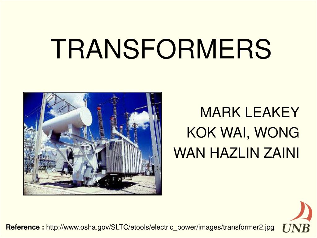
TRANSFORMERS. MARK LEAKEY KOK WAI, WONG WAN HAZLIN ZAINI. Reference : http://www.osha.gov/SLTC/etools/electric_power/images/transformer2.jpg. DEFINITION. Device used to transfer energy from primary winding to secondary winding by electromagnetic induction.
TRANSFORMERS - slide 1
01 / 18TRANSFORMERS
1 / 17

Télécharger la présentation

TRANSFORMERS
Une image / un lien ci-dessous est fourni (tel quel) pour télécharger la présentation

Politique de téléchargement : le contenu du site vous est fourni TEL QUEL pour votre information et votre usage personnel ; il ne peut être vendu, concédé sous licence ni partagé sur d’autres sites sans l’accord de son auteur.Le contenu vous est fourni TEL QUEL, pour votre information et votre usage personnel uniquement. Téléchargez la présentation en cliquant sur ce lien. Lors du téléchargement, si vous ne parvenez pas à télécharger une présentation, l’éditeur a peut-être supprimé le fichier de son serveur.Pendant le téléchargement, si vous ne parvenez pas à obtenir une présentation, le fichier a peut-être été supprimé par l’éditeur.

F I N

Plus de contenu associé

Transcription de la présentation
  1. TRANSFORMERS MARK LEAKEY KOK WAI, WONG WAN HAZLIN ZAINI Reference : http://www.osha.gov/SLTC/etools/electric_power/images/transformer2.jpg

  2. DEFINITION • Device used to transfer energy from primary winding to secondary winding by electromagnetic induction. • Based on Faraday’s Law of induction Where:- ε– EMF (V) ΦB– Magnetic flux (Wb)

  3. TRANSFORMER USES • Impedance matching • Electrical Isolation • AC power transmission • STEP-UP Transformer • STEP-DOWN Transformer

  4. HISTORY • 1831 – Michael Faraday invented the Induction Ring. • 1881 – Lucien Gaulard and John Gibbs exhibited a device called secondary generator. • 1885 – William Stanley developed the fist commercially used practical device while working for Westinghouse Electric Company in US.

  5. INDUCTION THEORY • Transformers behaviour is based on Faraday’s Law of Induction Where:- ε– EMF (V) N – No of turns of wire ΦB– Magnetic flux (Wb)

  6. INDUCTION THEORY Reference: http://www.tpub.com/doeelecscience/electrical%20science2_files/image1053.jpg

  7. TRANSFORMER MODELS Ideal Transformer Np = No of windings on the primary Ns = No of windings on the secondary ip = Current into the primary is = Current out from the secondary Vp = Voltage across the primary Vs = Voltage across the secondary

  8. Primary and Secondary Relationship VP = NP = a = iS VS NS iP Note; a < 1 = Step up transformer a > 1 = Step down transformer Voltage and current angles are NOT affected hence, θP = θS = θ

  9. LOSSES • Transformers have losses and these losses must come into consideration. • Copper losses (I^2 R) • Leakage Flux losses • Core losses • Eddy currents • Hysteresis losses

  10. REAL TRANSFORMER LOSSES • Copper losses (I^2 R) • Leakage Flux losses • Core losses • Eddy currents • Hysteresis losses

  11. EQUIVALENT CIRCUIT Approximate Transformer Model referred to the primary side

  12. IH ISE VSE NSE IL VH VL NC TYPES Auto-Transformer • Used to change a desirable voltage by only a small amount. For example: 120/132 V

  13. TYPES Three Phase Transformers • Three phase transformers • can be constructed in two • different ways i.e. :- • A three phase bank consists of three single phase transformers. • Three windings wrapped around a common core. Reference : Electric Machinery and Power System Fundamentals, Stephen J. Chapman

  14. THREE PHASE TRANSFORMER CONNECTIONS Delta – wye (Δ – Y) • Delta – delta (Δ – Δ) Wye – delta (Y- Δ) • Wye – wye (Y – Y) Reference : Electric Machinery and Power System Fundamentals, Stephen J. Chapman

  15. TYPES • Two types of special purpose transformers used in power systems for taking measurements. • Potential Transformer • Current Transformer Reference : Electric Machinery and Power System Fundamentals, Stephen J. Chapman

  16. EFFICIENCY • Efficiency (η) is the ratio of the power out to the power in of a transformer. • η in an Ideal transformer, no power losses • PIN = VPIP cos θP • POUT = VSIS cos θS • PIN = POUT = VPIP cos θP = VSIS cos θS • SOUT = SIN = VPIP = VSIS • ηIdeal = 100%

  17. Efficiency for a single phase real transformer • As mentioned previously, losses occur in a real transformer and these losses must be taken into count. • Hence, ηReal = POUT x 100% PIN = POUT x 100% POUT + PLOSS = VSIS cos θS_________ VSIS cos θS + i2R + (VP/a)2 RC

  18. VOLTAGE REGULATION • Voltage regulation (VR) is the ability of a system to provide near constant voltage over a wide range of load conditions. Also it compares the VO at no load to VO at full load. • An Ideal transformer has a voltage regulation, • VR = 0% Reference : http://en.wikipedia.org/wiki/Voltage_regulation