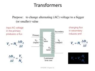
Transformers
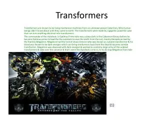
Learn about transformers, static devices that transfer electrical energy with desired voltage change, based on mutual induction. Explore construction types, ideal transformers, phasor diagrams, equivalent circuits, tests (O.C. and S.C.), and operational principles.


Transformers
E N D
Presentation Transcript
Transformer • It is a static device. • It transfers electrical energy from one electrical circuit to other with desired change in voltage and current, without changing the frequency(f=50Hz) and power. • Constant flux device • Magnetically coupled and electrically isolated • Electro magnetic conversion device.
Principle of operation It is based on principle of MUTUAL INDUCTION. According to which an e.m.f. is induced in a coil when current in the neighbouring coil changes.
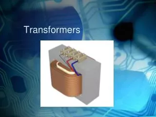
Constructional detail : Shell type • Parallel magnetic circuit • Windings are wrapped around the central limb of a laminated core. • Sandwitch winding to reduce the leakage flux • Less amount of copper & more amount of insulation is required
Constructional detail : Core type • Series magnetic circuit • Windings are wrapped around two sides of a laminated square core. • More amount of copper & less amount of insulation is required. • Economical for high voltage applications
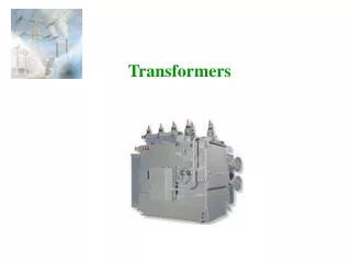
Sectional view of transformers Note: High voltage conductors are smaller cross section conductors than the low voltage coils
Core type Fig1: Coil and laminations of core type transformer Fig2: Various types of cores
Shell type • The HV and LV windings are split into no. of sections • Where HV winding lies between two LV windings • In sandwich coils leakage can be controlled Fig: Sandwich windings
Working of a transformer 1. When current in the primary coil changes being alternating in nature, a changing magnetic field is produced 2. This changing magnetic field gets associated with the secondary through the soft iron core 3. Hence magnetic flux linked with the secondary coil changes. 4. Which induces e.m.f. in the secondary.
Ideal Transformers • Zero leakage flux: -Fluxes produced by the primary and secondary currents are confined within the core • The windings have no resistance: - Induced voltages equal applied voltages • The core has infinite permeability - Reluctance of the core is zero - Negligible current is required to establish magnetic flux • Loss-less magnetic core - No hysteresis or eddy currents
Ideal transformer V1 – supply voltage ; I1- noload input current ; V2- output voltgae; I2- output current Im- magnetising current; E1-self induced emf ; E2- mutually induced emf
Transformer on load assuming no voltage drop in the winding • Fig shows the Phasor diagram of a transformer on load by assuming • No voltage drop in the winding • Equal no. of primary and secondary turns
Transformer on load Fig. a: Ideal transformer on load Fig. b: Main flux and leakage flux in a transformer
Equivalent circuit of a transformer No load equivalent circuit:
Equivalent circuit parameters referred to primary and secondary sides respectively
Transferring secondary parameters to primary side Cu loss after transfer = cu loss before transfer Where R21 - Equivalent secondary resistance w.r.t primary R01 = R1 + R21 Where R01– Total primary resistance referred to secondary
Transferring primary parameters to secondary side : Cu loss after transfer = cu loss before transfer = k2 R1 Where R11 - Equivalent primary resistance w.r.t secondary R02 = R2 + R11 Where R01– Total secondary resistance referred to primary
Approximate equivalent circuit Since the no load current is 1% of the full load current, the no load circuit can be neglected
Transformer Tests • The performance of a transformer can be calculated on the basis of equivalent circuit • The four main parameters of equivalent circuit are: • - R01 as referred to primary (or secondary R02) • - the equivalent leakage reactance X01as referred to primary (or secondary X02) • - Magnetising susceptance B0 ( or reactance X0) • - core loss conductance G0 (or resistance R0) • The above constants can be easily determined by two tests • - Oper circuit test (O.C test / No load test) • - Short circuit test (S.C test/Impedance test) • These tests are economical and convenient • - these tests furnish the result without actually loading the transformer Electrical Machines
Open-circuit Test In Open Circuit Test the transformer’s secondary winding is open-circuited, and its primary winding is connected to a full-rated line voltage. • Usually conducted on H.V side • To find (i) No load loss or core loss (ii) No load current Io which is helpful in finding Go(or Ro ) and Bo (or Xo )
Short-circuit Test In Short Circuit Test the secondary terminals are short circuited, and the primary terminals are connected to a fairly low-voltage source The input voltage is adjusted until the current in the short circuited windings is equal to its rated value. The input voltage, current and power is measured. • Usually conducted on L.V side • To find (i) Full load copper loss – to pre determine the efficiency (ii) Z01 or Z02; X01 or X02; R01 or R02 - to predetermine the voltage regulation
Voltage regulation of a transformer recall Secondary voltage on no-load V2 is a secondary terminal voltage on full load Substitute we have
Transformer Efficiency Transformer efficiency is defined as (applies to motors, generators and transformers): • Types of losses incurred in a transformer: • Copper I2R losses • Hysteresis losses • Eddy current losses • Therefore, for a transformer, efficiency may be calculated using the following: Electrical Machines
Losses in a transformer Core or Iron loss: Total cu losses = = =
All day efficiency : The load at which the two losses are equal = • All day efficiency is always less than the commercial efficiency