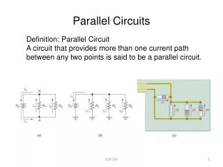
Parallel Circuits in Electronics
Learn about types of circuits, particularly parallel circuits, where current flows through multiple paths. Explore concepts of voltage, resistance, and safety precautions. Additional information provided through animations and practice exercises.

Parallel Circuits in Electronics
E N D
Presentation Transcript
Types of Circuits: Parallel A parallel circuit can be constructed by connecting light bulbs in such a manner that there are SEVERAL PATHS for charge flow (CURRENT); the light bulbs are placed within a separate branch line, and a charge moving through the circuit will pass through only one of the branches during its path back to the low potential (negative) terminal of the battery. Since there is now several current paths, the total current of the circuit equals the sum of the current in each branch. I = I1 + I2 + I3
Types of Circuits: Parallel Does this hold true? I = I1 + I2 + I3 Let’s take a closer look at how the current is flowing through each branch. 12 A 9 A 9 A 6 A 6 A 3 A 3 A 6 A 3 A 3 A 9 A 6 A 6 A 12 A 9 A
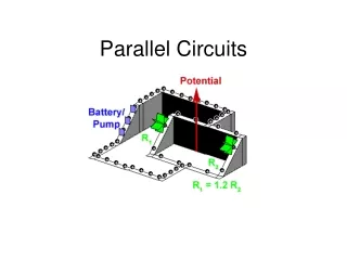
Types of Circuits: Parallel Let’s look at voltage: Each branch is hooked up to the same battery. Each branch has the same voltage (electric pressure). V = V1 = V2 = V3 Outlets in a house are connected in parallel so you can use one appliance without having to turn them all on.
Types of Circuits: Parallel Let’s look at RESISTANCE: The actual amount of current always varies inversely with the amount of overall resistance. I = V Req 1 = 1 + 1 + 1 Req R1 R2 R3
Types of Circuits: Parallel The total resistance of a parallel circuit is a fraction of all of the resistors added together!!!! 1 = 1 + 1 + 1 Req R1 R2 R3
Types of Circuits: Parallel I = V Req So the more resistors you add in parallel the lower the equivalent resistance will be. And because Req the I sometimes to a potentially dangerous level. This is why we have circuit breakers or fuses inserted into the main line of our homes. When we are trying to use too many electrical devices (resistors) in parallel the current gets to be too much and a fuse in blown. http://phet.colorado.edu/sims/ohms-law/ohms-law_en.html
Inside the fuse is a small piece of metal, across which current must pass. During normal flow of current, the fuse allows the current to pass unobstructed. But during an unsafe overload, the small piece of metal melts, stopping the flow of current. Circuit breakers are switches that are tripped when the current flow passes a unsafe limit. The excess of current typically triggers an electromagnet, which trips the circuit breaker when an unsafe limit is reached. Once tripped, the switches simply turn off. That stops the flow of electricity, which will remain off until the switch is reset.
Parallel Summary: I = I1 + I2 + I3 V = V1 = V2 = V3 1 = 1 + 1 + 1 Req R1 R2 R3
In this animation you should notice the following things: • More current flows through the smaller resistance. (More charges take the easiest path.) • The battery or source is represented by an escalator which raises charges to a higher level of energy. • As the charges move through the resistors (represented by the paddle wheels) they do work on the resistor and as a result, they lose electrical energy. • By the time each charge makes it back to the battery, it has lost all the electrical energy given to it by the battery. • The total of the potential drops ( - potential difference) of each "branch" or path is the same as the potential rise ( + potential difference) across the battery. This demonstrates that a charge can only do as much work as was done on it by the battery. • The charges are positive so this is a representation of conventional current(the apparent flow of positive charges) • The charges are only flowing in one direction so this would be considered direct current ( D.C. ). 30 Ω 10 Ω
Series vs. Parallel The more resistors you have the less the equivalent resistance is, and current increases. Voltage never changes. I = I1 + I2 + I3 I = I1 = I2 = I3 V = V1 = V2 = V3 V = V1 + V2 + V3 1 = 1 + 1 + 1 Req R1 R2 R3 Req = R1 + R2 + R3 The more resistors you have the more the equivalent resistance is, and current never changes. The voltage across each resistor adds up to the total voltage of the source (battery).
Hooking up Devices Properly Ammeters, because of the way they are built, have very little resistance. So they can be placed in series with other devices in a circuit and not disrupt the current. It would be just like putting a low resistor in the circuit. A A If you placed an ammeter in parallel you would never be able to measure the total current of a circuit because parallel branches don’t have the same current as the total current of the circuit.
Hooking up Devices Properly Voltmeters on the other hand have a very high resistance and when placed in series would disrupt the current so they are placed in parallel within the circuit- in a separate branch. V V Also, think about what a voltmeter is measuring…the potential difference ACROSS a resistor or a battery. The device needs to be places ACROSS a resistor or battery.
CW Practice #1: 12 V 4 Ω 6 Ω 12 Ω
CW Practice #1 Solution: 12 V 4 Ω 6 Ω 12 Ω I = I1 + I2 + I3 V = V1 = V2 = V3 1 = 1 + 1 + 1 Req R1 R2 R3 a.1 = 1 + 1 + 1 Req R1 R2 R3 1 = 1 + 1 + 1 Req 4 Ω 6 Ω 12 Ω Need a common denominator NOTE: Notice how the Req is less than any of the resistors in the circuit. 1 = 3 + 2 + 1 Req 12 Ω 12 Ω 12 Ω 1 = 6 Req 12 Ω Req = 12 Ω 1 6 = 2 Ω
I1 = V R1 I1 = 12 V 4 Ω I1 = 3 A b. V = V1 = V2 = V3 I3 = V R3 V = 12 V 12 V 4 Ω 6 Ω 12 Ω I3 = 12 V 12 Ω I3 = 1 A • I = V R I2 = V R2 I2 = 12 V 6 Ω I2 = 2 A
d. Power=? P3 = VI3 = 12V(1A) = 12W P2 = VI2 = 12V(2A) = 24W P1 = VI1 = 12V(3A) =36W PT = P1 + P2 + P3 = 36W + 24W + 12W = 72W
CW Practice #2: A1 A2 12 V 10 Ω 15 Ω A3
CW Practice #1 Solution: A1 A2 I = I1 + I2 + I3 12 V 10 Ω 15 Ω V = V1 = V2 = V3 1 = 1 + 1 + 1 Req R1 R2 R3 A3 A2 = I2 = V R2 A3 = I1+ I2 a. A1 = I1 = V R1 A3 =1.2A + .8A I2 = 12 V 15 Ω I1 = 12 V 10 Ω A3 = 2 A I2 = .8 A I1 = 1.2 A
b. V = V1 = V2 A1 A2 V = 12 V 12 V 10 Ω 15 Ω c. 1 = 1 + 1 Req R1 R2 A3 1 = 1 + 1 Req 10 Ω 15 Ω 1 = 3 + 2 Req 30 Ω 30 Ω 1 = 5 Req 30 Ω Req = 30 Ω 1 5 = 6 Ω
d. Power=? P2 = VI2 = 12V(.8A) = 9.6W P1 = VI1 = 12V(1.2A) =14.4W PT = P1 + P2 + P3 = 14.4W + 9.6W = 24W
HW Practice #2: 12 V = 10 Ω = 5 Ω = 20 Ω
HW Practice #3: =120V =4 A =.571 A =1.71 A
Which two of the resistor arrangements below have the same equivalent resistance? 1 Ω 1 Ω A 8 Ω B 8 Ω 2 Ω 2 Ω C 2 Ω D 2 Ω
Which circuit below would have the lowest voltmeter reading? 6 V 6 V A 20 Ω C V 20 Ω 40 Ω V 40 Ω 6 V 6 V 20 Ω B D 20 Ω 40 Ω 40 Ω V V
Arrange the schematic diagrams below in order of increasing equivalent resistance. 1 2 3 4
Find the resistance of R3. Req = 2 Ω R1 = 6 Ω R2 = 6 Ω R3 = ? 1 = 1 + 1 + 1 Req R1 R2 R3