Parallel Circuits
This guide covers the fundamentals of parallel circuits in physics, detailing how multiple resistors function through various pathways. It explains that electrons can choose any path, with more flowing through those offering less resistance. You'll learn how to calculate total resistance, using formulas for current in each path based on individual resistances. This overview also highlights how adding resistors reduces overall resistance and explains the impact of disconnecting a resistor on circuit functionality.


Parallel Circuits
E N D
Presentation Transcript
Parallel Circuits Principles of Physics
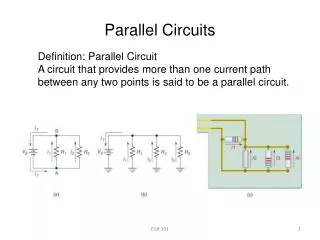
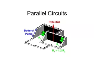
Figure 3 Parallel Circuit • More than one resistor in multiple paths • Electrons may go through any path • More electrons will go through path with less resistance • Overall resistance goes down because more than one electron can get through at once R2 R1
Series versus PArallel One connection between resistors Two connections between resistors
Figure 3 Current in a Parallel Circuit • Current flow is different in each path depending on the individual resistance I1 = V1/R1 • Total current (current leaving or entering the voltage supply) depends on total resistance IT = VT/RT • Current in all paths add up to the total current leaving the supply IT = I1 + I2 + … R2 R1
Figure 3 Voltage in a Parallel Circuit • Voltage gained by electrons when leaving the voltage supply equals the voltage lost before returning • Since each electron takes a separate path it must lose all of its voltage through the resistor in that path VT = V1 = V2 = … R2 R1
Figure 3 Total Resistance in a Parallel Circuit To determine the current leaving the voltage supply the total resistance must be used 1 RT = 1 + 1 + … R1 R2 R2 R1
Figure 3 Calculating Total Resistance in Parallel Circuits Determine the total resistance in the circuit at left if R1 = 6 Ω and R2 = 6 Ω 1 RT = 1 + 1 R1 R2 1 RT = 1 + 1 6 6 1 1 RT = 0.167 + 0.167 = 0.333 RT = 3 Ω R2 R1
Figure 3 Analyzing a Parallel Circuit Determine the total resistance of the circuit. 1 RT = 1 + 1 R1 R2 1 RT = 1 + 1 4 4 1 1 RT = 0. 25 + 0.25 = 0.5 RT = 2 Ω 4 Ω 12 V 4 Ω
Figure 3 Analyzing a Parallel Circuit Determine the total current of the circuit. V = IR 12 = I(2) I = 6 A 4 Ω 12 V 4 Ω
Figure 3 Analyzing a Parallel Circuit Determine the current through each of the resistors V = IR 12 = I(4 ) I = 3 A 4 Ω 12 V 4 Ω
Resistors in Parallel • Adding a resistor in parallel decreases the overall resistance • Total resistance will be less than any of the individual resistors • When one resistor is disconnected only that path is open – current flows in the rest of the circuit (light bulbs will stay lit) • Everyone picks one door to get out • Most will go through largest door