Parallel Circuits
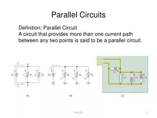
Parallel Circuits. Lecture No.5 By – Engr Sajid Hussain Qazi Mehran U.E.T Campus Khairpur. Parallel Circuits. “Two elements, branches, or networks are in parallel if they have two points in common.”

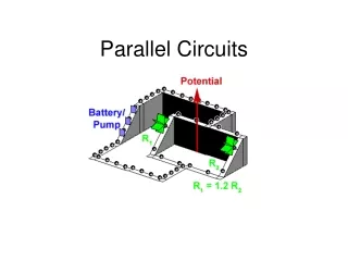
Parallel Circuits
E N D
Presentation Transcript
Parallel Circuits Lecture No.5 By – EngrSajidHussainQazi Mehran U.E.T Campus Khairpur
Parallel Circuits • “Two elements, branches, or networks are in parallel if they have two • points in common.” • In Fig. 1, elements 1 and 2 have terminals a and b in common; they are therefore in parallel. • In Fig. 2, all the elements are in parallel because they satisfy the above criterion. Three configurations are provided to demonstrate how the parallel networks can be drawn. Engr. S.H.Qazi FIGURE-1
FIGURE-2 In Fig.3, elements 1 and 2 are in parallel because they have terminals a and b in common. The parallel combination of 1 and 2 is then in series with element 3 due to onecommon terminal point b. FIGURE-3 Engr. S.H.Qazi
Total Conductance and Resistance • Recall that for series resistors, the total resistance is the sum of the resistor values. • For parallel elements, • “The total conductance is the sum of the individual conductance.” • That is, for the parallel network of Fig. 4, we write G-Conductance FIGURE-4 Engr. S.H.Qazi
Since increasing levels of conductance will establish higher current levels, the more terms appearing in above equation, the higher the input current level. In other words, as the number of resistors in parallel increases, the input current level will increase for the same applied voltage, the opposite effect of increasing the number of resistors in series. Substituting resistor values for the network of Fig.4, will result in the network of Fig. 5. Since G=1/R, the total resistance for the network can be determined by direct substitution into Equation. FIGURE-5 Engr. S.H.Qazi
EXAMPLE.1 Determine the total conductance and resistance for the parallel network of Figure shown. EXAMPLE.2 Determine the effect on the total conductance and resistance of the network of Figure, if another resistor of 10 ohms were added in parallel with the other elements. Solution. Solution. Note, as mentioned above, that adding additional terms increases the conductance level and decreases the resistance level. Engr. S.H.Qazi
EXAMPLE .3 Determine the total resistance for the network shown below. For same value of resistors, the equation for finding Rt, becomes more easier to apply. For N equals resistors in parallel, equation becomes.. Engr. S.H.Qazi
EXAMPLE .4 Determine the total resistance for the networks shown below. Answer-4 ohms Answer-0.5 ohms When number of resistors in circuit are two, then total resistance can be found by using below formula. Engr. S.H.Qazi
Exercise Problem Example.5. Determine total resistance of circuit shown in fig.1. (b) What is the effect on total resistance of fig.1 if an additional resistor of same value is added in parallel as shown in fig.2. (c) What is the effect on total resistance of fig.1 if a large resistance is added in parallel as shown in fig.3. (d) What is the effect on total resistance of fig.1 if a small resistance is added in parallel as shown in fig.4. Fig.3 (15 ohm) Fig.1 (14.77 ohm) Engr. S.H.Qazi (10 ohm) Fig.4 (0.099 ohm) Fig.2
Current Divider Rule • As the name suggests, the current divider rule (CDR) will determine how the current entering a set of parallel branches will split between the elements. • “For two parallel elements of equal value, the current will divide equally.” • “For parallel elements with different values, the smaller • the resistance, the greater the share of input current.” • “For parallel elements of different values, the current will split with a ratio equal to the inverse of their resistor values.” • For example, if one of two parallel resistors is twice the other, then the current through the larger resistor will be half the other. Engr. S.H.Qazi
In Fig. 6, since I1 is 1 mAand R1 is six times R3, the current through R3 must be 6 mA. For R2 the current must be 2 mAsince R1 is twice R2. The total current must then be the sum of I1, I2, and I3. FIGURE-6 For networks in which only the resistor values are given along with the input current, the current divider rule should be applied to determine the various branch currents. It can be derived using the network of Fig. 7. Engr. S.H.Qazi
Input Current I equals Substituting V=IxRxin above equation This is the general form for the current divider rule. In words, the current through any parallel branch is equal to “The product of the total resistance of the parallel branches and the input current divided by the resistance of the branch through which the current is to be determined.” For the current I1, For the current I2, And so on…. Engr. S.H.Qazi
For the particular case of two parallel resistors, as shown in Fig.7. FIGURE-7 For I2, Engr. S.H.Qazi
Example 6. Determine current I2 for network shown. Example 7. Determine current I1 for circuit shown. Engr. S.H.Qazi
Example 8. Determine current I1, I2 and I3 for circuit shown. Also verify KCL. Using CDR Applying KCL For verification, using CDR Total current entering the branch must equal to leaving.. Engr. S.H.Qazi
Practice Example Example 9. Determine resistance R1 for circuit shown. (R2=2 ohm) Engr. S.H.Qazi
PRACTICE TEST Q.1. Two branches will be in parallel if they have ______ terminals in common. TWO Q.2. Opposite of resistance is_______ and its unit is __________. Conductance/ Siemen Q.3. If number of parallel resistors increases the value of _______________ increases for the same applied __________. Input Current/Voltage Q.4. In parallel circuits relation of current and resistance is ___________. Inverse Engr. S.H.Qazi