PARALLEL CIRCUITS
This chapter on parallel circuits explores the fundamental characteristics of electrical circuits with multiple pathways for current flow. It outlines the key rules governing parallel circuits, including the total current being the sum of branch currents, the voltage across each branch equaling the applied voltage, and how to calculate total resistance as the reciprocal of the sum of branch reciprocals. It also discusses the rationale behind connecting homes and car circuits in parallel and explains why parallel circuits are known as current dividers. Finally, the chapter reviews how power is dissipated in parallel configurations.

PARALLEL CIRCUITS
E N D
Presentation Transcript
PARALLEL CIRCUITS CHAPTER 7
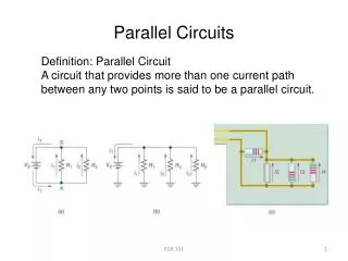
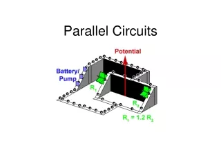
PARALLEL CIRCUITSDEFINITION • A CIRCUIT THAT HAS MORE THAN ONE PATH FOR CURRENT FLOW
PARALLEL CIRCUIT RULES • TOTAL CURRENT IS SUM OF THE CURRENTS THROUGH ALL THE BRANCHES • VOLTAGE ACROSS ANY BRANCH EQUALS APPLIED VOLTAGE • TOTAL RESISTANCE IS THE RECIPROCAL OF THE SUM OF RECIPROCALS OF EACH BRANCH “AND” IS ALWAYS LESS THAN SMALLEST BRANCH
VOLTAGE TO EACH BRANCH IS APPLIED VOLTAGE TOTAL RESISTANCE IS LESS THAN SMALLLEST BRANCH
GIVE DEFINITION OF A PARALLEL CIRCUIT. STATE THE THREE RULES FOR PARALLEL CIRCUITS. WHY ARE HOMES CONNECTED IN PARALLEL? WHAT CIRCUITS ARE CONNECTED IN PARALLEL ON CARS? WHY ARE PARALLEL CIRCUITS CALLED CURRENT DIVIDERS? HOW IS POWER DISSIPATED IN A PARALLEL? REVIEW