Download
1 / 49
490 likes | 554 Vues
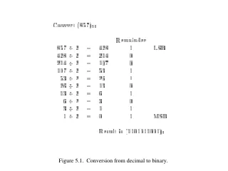
Figure 5.1. Conversion from decimal to binary. Table 5.1. Numbers in different systems. Please see “ portrait orientation ” PowerPoint file for Chapter 5. Figure 5.2. Half-adder. Figure 5.3. An example of addition. Please see “ portrait orientation ” PowerPoint file for Chapter 5.

E N D
Please see “portrait orientation” PowerPoint file for Chapter 5 Figure 5.2. Half-adder.
Please see “portrait orientation” PowerPoint file for Chapter 5 Figure 5.4. Full-adder.
s c s i i HA c s x i c HA c i + 1 y i (a) Block diagram c i s i x i y i c i + 1 (b) Detailed diagram Figure 5.5. A decomposed implementation of the full-adder circuit.
x y x y x y 1 1 0 0 n – 1 n – 1 c 1 c c c c FA FA FA n ” 1 n 0 2 s s s n – 1 1 0 MSB position LSB position Figure 5.6. An n-bit ripple-carry adder.
Please see “portrait orientation” PowerPoint file for Chapter 5 Figure 5.7. Circuit that multiplies an 8-bit unsigned number by 3.
b b b n – 1 1 0 Magnitude MSB (a) Unsigned number b b b b n – 1 n – 2 1 0 Magnitude Sign 0 denotes + – MSB 1 denotes (b) Signed number Figure 5.8. Formats for representation of integers.
( – 5 ) ( ) + 5 0 1 0 1 1 0 1 0 ( ) ( ) + + 2 + + 0 0 1 0 0 0 1 0 + + 2 ( ) ( - 3 ) + 7 0 1 1 1 1 1 0 0 ( ) + 5 0 1 0 1 1 0 1 0 ( – 5 ) + + + ( – 2 ) 1 1 0 1 1 1 0 1 + ( – 2 ) ( ) ( – 7 ) + 3 1 0 0 1 0 1 0 1 1 1 1 1 0 0 1 1 1 0 0 0 Figure 5.9. Examples of 1’s complement addition.
( ) ( ) + 5 0 1 0 1 – 5 1 0 1 1 ( ) ( ) + + 2 + + + 2 + 0 0 1 0 0 0 1 0 ( ) – 3 ( ) + 7 0 1 1 1 1 1 0 1 ( ) ( ) + 5 0 1 0 1 – 5 1 0 1 1 ( ) ( ) + + + + 1 1 1 0 – 2 1 1 1 0 – 2 ( ) – 7 ( ) + 3 1 0 0 1 1 1 1 0 0 1 ignore ignore Figure 5.10. Examples of 2’s complement addition.
( ) + 5 0 1 0 1 0 1 0 1 ( ) – + 2 – + 0 0 1 0 1 1 1 0 ( ) + 3 1 0 0 1 1 ignore ( ) 1 0 1 1 1 0 1 1 – 5 ( ) + 2 – – + 0 0 1 0 1 1 1 0 ( ) 1 1 0 0 1 – 7 ignore ( ) + 5 0 1 0 1 0 1 0 1 ( ) – + – – 2 1 1 1 0 0 0 1 0 ( ) + 7 0 1 1 1 ( ) 1 0 1 1 1 0 1 1 – 5 ( ) – + – – 2 1 1 1 0 0 0 1 0 1 1 0 1 ( ) – 3 Figure 5.11. Examples of 2’s complement subtraction.
0000 1111 0001 1110 0010 0 – 1 + 1 – 2 + 2 1101 0011 – 3 + 3 – 4 + 4 1100 0100 – 5 + 5 1011 0101 – 6 + 6 – 7 + 7 – 8 1010 0110 1001 0111 1000 Figure 5.12. Graphical interpretation of four-bit 2’s complement numbers.
y y y n – 1 1 0 ¤ Add Sub control x x x n – 1 1 0 c c n -bit adder 0 n s s s n – 1 1 0 Figure 5.13. Adder/subtractor unit.
( ) ( ) + 7 0 1 1 1 – 7 1 0 0 1 ( ) ( ) + 2 + + 2 + + + 0 0 1 0 0 0 1 0 ( ) – 5 ( ) + 9 1 0 0 1 1 0 1 1 c = 0 c = 0 4 4 c = 1 c = 0 3 3 ( ) ( ) + 7 0 1 1 1 – 7 1 0 0 1 ( ) ( ) + + + + – 2 – 2 1 1 1 0 1 1 1 0 ( ) – 9 ( ) + 5 1 0 1 0 1 1 0 1 1 1 c = 1 c = 1 4 4 c = 1 c = 0 3 3 Figure 5.14. Examples of determination of overflow.
x y x y 1 1 0 0 g p g p 1 1 0 0 c 1 c c 0 2 Stage 1 Stage 0 s s 1 0 Figure 5.15. A ripple-carry adder with generate/propagate signals.
x y x y 1 1 0 0 x y 0 0 g p g p 1 1 0 0 c 0 c 2 c 1 s s 1 0 Figure 5.16. The first two stages of a carry-lookahead adder.
x y x y x y 15 – 8 15 – 8 7 – 0 7 – 0 31 – 24 31 – 24 c 8 Block Block Block c c c c 32 24 16 0 3 1 0 s s s 31 – 24 15 – 8 7 – 0 Figure 5.17. A hierarchical carry-lookahead adder with ripple-carry between blocks.
x y x y x y 31 – 24 31 – 24 15 – 8 15 – 8 7 – 0 7 – 0 Block Block Block c 0 3 1 0 c 24 G P G P G P 3 3 1 1 0 0 s s s 31 – 24 15 – 8 7 – 0 c c c 32 16 8 Second-level lookahead Figure 5.18. A hierarchical carry-lookahead adder.
x y x y 1 1 0 0 g p g p 1 1 0 0 c 0 c 2 c 1 s s 1 0 Figure 5.19. An alternative design for a carry-lookahead adder.
Figure 5.20. Schematic using an LPM adder/subtractor module.
Figure 5.21. Simulation results for the LPM adder optimized for cost.
Figure 5.22. Simulation results for the LPM adder optimized for speed.
module fulladd (Cin, x, y, s, Cout); input Cin, x, y; output s, Cout; xor (s, x, y, Cin); and (z1, x, y); and (z2, x, Cin); and (z3, y, Cin); or (Cout, z1, z2, z3); endmodule Figure 5.23. Verilog code for the full-adder using gate level primitives.
module fulladd (Cin, x, y, s, Cout); input Cin, x, y; output s, Cout; xor (s, x, y, Cin); and (z1, x, y), (z2, x, Cin), (z3, y, Cin); or (Cout, z1, z2, z3); endmodule Figure 5.24. Another version of Verilog code from Figure 5.23.
module fulladd (Cin, x, y, s, Cout); input Cin, x, y; output s, Cout; assign s = x ^ y ^ Cin; assign Cout = (x & y) | (x & Cin) | (y & Cin); endmodule Figure 5.25. Verilog code for the full-adder using continuous assignment.
module fulladd (Cin, x, y, s, Cout); input Cin, x, y; output s, Cout; assign s = x ^ y ^ Cin, Cout = (x & y) | (x & Cin) | (y & Cin); endmodule Figure 5.26. Another version of Verilog code from Figure 5.25.
module adder4 (carryin, x3, x2, x1, x0, y3, y2, y1, y0, s3, s2, s1, s0, carryout); input carryin, x3, x2, x1, x0, y3, y2, y1, y0; output s3, s2, s1, s0, carryout; fulladd stage0 (carryin, x0, y0, s0, c1); fulladd stage1 (c1, x1, y1, s1, c2); fulladd stage2 (c2, x2, y2, s2, c3); fulladd stage3 (c3, x3, y3, s3, carryout); endmodule module fulladd (Cin, x, y, s, Cout); input Cin, x, y; output s, Cout; assign s = x ^ y ^ Cin, assign Cout = (x & y) | (x & Cin) | (y & Cin); endmodule Figure 5.27. Verilog code for a four-bit adder.
module adder4 (carryin, X, Y, S, carryout); input carryin; input [3:0] X, Y; output [3:0] S; output carryout; wire [3:1] C; fulladd stage0 (carryin, X[0], Y[0], S[0], C[1]); fulladd stage1 (C[1], X[1], Y[1], S[1], C[2]); fulladd stage2 (C[2], X[2], Y[2], S[2], C[3]); fulladd stage3 (C[3], X[3], Y[3], S[3], carryout); endmodule Figure 5.28. A four-bit adder using vectors.
module addern (carryin, X, Y, S, carryout); parameter n=32; input carryin; input [n-1:0] X, Y; output [n-1:0] S; output carryout; reg [n-1:0] S; reg carryout; reg [n:0] C; integer k; always @(X or Y or carryin) begin C[0] = carryin; for (k = 0; k < n; k = k+1) begin S[k] = X[k] ^ Y[k] ^ C[k]; C[k+1] = (X[k] & Y[k]) | (X[k] & C[k]) | (Y[k] & C[k]); end carryout = C[n]; end endmodule Figure 5.29. A generic specification of a ripple-carry adder.
module addern (carryin, X, Y, S); parameter n = 32; input carryin; input [n-1:0] X, Y; output [n-1:0] S; reg [n-1:0] S; always @(X or Y or carryin) S = X + Y + carryin; endmodule Figure 5.30. Specification of an n-bit adder using arithmetic assignment.
module addern (carryin, X, Y, S, carryout, overflow); parameter n = 32; input carryin; input [n-1:0] X, Y; output [n-1:0] S; output carryout, overflow; reg [n-1:0] S; reg carryout, overflow; always @(X or Y or carryin) begin S = X + Y + carryin; carryout = (X[n-1] & Y[n-1]) | (X[n-1] & ~S[n-1]) | (Y[n-1] & ~S[n-1]); overflow = carryout ^ X[n-1] ^ Y[n-1] ^ S[n-1]; end endmodule Figure 5.31. An n-bit adder with carry-out and overflow signals.
module addern (carryin, X, Y, S, carryout, overflow); parameter n = 32; input carryin; input [n-1:0] X, Y; output [n-1:0] S; output carryout, overflow; reg [n-1:0] S; reg carryout, overflow; reg [n:0] Sum; always @(X or Y or carryin) begin Sum = {1'b0,X} + {1'b0,Y} + carryin; S = Sum[n-1:0]; carryout = Sum[n]; overflow = carryout ^ X[n-1] ^ Y[n-1] ^ S[n-1]; end endmodule Figure 5.32. An alternative specification of an n-bit adder with carry-out and overflow signals.
module addern (carryin, X, Y, S, carryout, overflow); parameter n = 32; input carryin; input [n-1:0] X, Y; output [n-1:0] S; output carryout, overflow; reg [n-1:0] S; reg carryout, overflow; always @(X or Y or carryin) begin {carryout, S} = X + Y + carryin; overflow = carryout ^ X[n-1] ^ Y[n-1] ^ S[n-1]; end endmodule Figure 5.33. Simplified complete specification of an n-bit adder.
module fulladd (Cin, x, y, s, Cout); input Cin, x, y; output s, Cout; reg s, Cout; always @(x or y or Cin) {Cout, s} = x + y + Cin; endmodule Figure 5.34. Behavioral specification of a full-adder.
Please see “portrait orientation” PowerPoint file for Chapter 5 Figure 5.35. Multiplication of unsigned numbers.
Please see “portrait orientation” PowerPoint file for Chapter 5 Figure 5.36. A 4 x 4 multiplier circuit.
Please see “portrait orientation” PowerPoint file for Chapter 5 Figure 5.37. Multiplication of signed numbers.
32 bits S E M Sign 8-bit 23 bits of mantissa + 0 denotes excess-127 – 1 denotes exponent (a) Single precision 64 bits S M E Sign 11-bit excess-1023 52 bits of mantissa exponent (c) Double precision Figure 5.38. IEEE standard floating-point formats.
X 0 1 1 1 7 + + + Y 0 1 0 1 5 Z 1 1 0 0 12 + 0 1 1 0 carry 1 0 0 1 0 S = 2 X 1 0 0 0 8 + + + Y 1 0 0 1 9 Z 1 0 0 0 1 17 + 0 1 1 0 carry 1 0 1 1 1 S = 7 Figure 5.39. Addition of BCD digits.
module bcdadd (Cin, X, Y, S, Cout); input Cin; input [3:0] X, Y; output [3:0] S; output Cout; reg [3:0] S; reg Cout; reg [4:0] Z; always @ (X or Y or Cin) begin Z = X + Y + Cin; if (Z < 10) {Cout, S} = Z; else {Cout, S} = Z + 6; end endmodule Figure 5.41. Verilog code for a one-digit BCD adder.
Figure 5.42. Functional simulation of the Verilog code in Figure 5.41.
module problem5_17 (IN, OUT); input [3:0] IN; output [3:0] OUT; reg [3:0] OUT; always @(IN) if (IN == 4'b0101) OUT = 4'b0001; else if (IN == 4'b0110) OUT = 4'b0010; else if (IN == 4'b0111) OUT = 4'b0011; else if (IN == 4'b1001) OUT = 4'b0010; else if (IN == 4'b1010) OUT = 4'b0100; else if (IN == 4'b1011) OUT = 4'b0110; else if (IN == 4'b1101) OUT = 4'b0011; else if (IN == 4'b1110) OUT = 4'b0110; else if (IN == 4'b1111) OUT = 4'b1001; else OUT = 4'b0000; endmodule Figure P5.2. The code for problem 5.17.
0 0 0 0 0 1 0 1 0 2 0 2 1 0 0 1 1 1 0 2 1 2 1 0 2 0 0 2 2 1 1 0 2 2 1 1 Figure P5.3. Ternary half-adder.