Download

1 / 13
140 likes | 380 Vues
Explore the application of mixed electrical and thermal modeling using a SPICE-style BJT model, bond graph conversion, and thermodynamic considerations. Understand the problematic aspects of the SPICE BJT model and obtain a modified BJT model.

E N D
In this class, we shall deal with an application of mixed electrical and thermal modeling: the Bipolar Junction Transistor (BJT). We shall start out with a SPICE-style model of the BJT, then convert the model to a bond graph. We shall recognize that the SPICE-model of the BJT is problematic. We shall convert the bond graph to obtain a modified BJT model that makes sense from a thermodynamic point of view. Modeling of Bipolar Transistors
BJT model Vertical and lateral npn-transistor Non-linear current source Junction diode BJT bond graph Power-flow interpretation Modified BJT bond graph Table of Contents
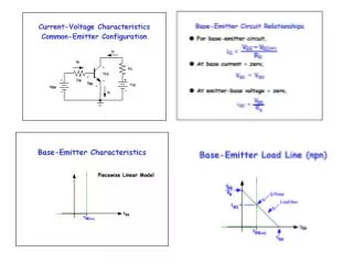
SPICE-style BJT Model SPICE models the BJT by three junction diodes, one from the base to the collector, the second from the base to the emitter, and the third to the substrate. The figure to the left shows a laterally diffused npn-transistor.
vertical lateral Vertical and Lateral npn-Transistors • The pnjunction diodes connect positively doped regions with negatively doped regions. • In the laterally diffused BJT, all three junction diodes have their anodes in the base. Dopants: for p-region (acceptors): boron or aluminum for n-region (donors): phosphorus or arsenic
Non-linear Current Sources • The model contains two non-linear current sources that inject currents into the circuit: • The current injected into the collector is a function of the base-emitter Voltage, and the current injected into the emitter is a function of the base-collector Voltage.
Jd The Junction Diode Model • The pn junction diode is modeled as follows:
Converted using the diamond property The BJT Bond Graph
Where does the power for these current sources come from? The sources are internal to the model. Hence there is no place where these sources could possibly draw power from. Problems With BJT Bond Graph
The two current sources are really a power sink, rather than a power source. They can be interpreted as a single non-linear resistor. The Non-linear Resistor
Dissipated Power I • The power dissipated by the RS-element of the junction diodes (i.e., the two former current “sources”) is: • and therefore: • We still need to show that PBJT > 0.
Dissipated Power II • We need to show that VC’E’ and iCE always point in the same direction.
Cellier, F.E. (1991), Continuous System Modeling, Springer-Verlag, New York, Chapter 6. Schweisguth, M.C. (1997), Semiconductor Modeling with Bondgraphs, MS Thesis, Dept. of Electr. & Comp. Engr., University of Arizona, Tucson, AZ. Schweisguth, M.C. and F.E. Cellier (1999), A Bond Graph Model of the Bipolar Junction Transistor, Proc. SCS Intl. Conf. on Bond Graph Modeling, San Francisco, CA, pp. 344-349. References