Download
1 / 10
100 likes | 127 Vues
Technical Drawing in Photonics Lesson 1 Necessity of technical (engineering) drawings. Standards of technical (engineering) drawings. Dr. Zsolt István Benkő. TAMOP-4.1.1.C-12/1/KONV-2012-0005 project.

E N D
Technical Drawing in Photonics • Lesson 1 • Necessity of technical (engineering) drawings. • Standards of technical (engineering) drawings. Dr. Zsolt István Benkő TAMOP-4.1.1.C-12/1/KONV-2012-0005 project „Preparation of the concerned sectors for educational and R&D activities related to the Hungarian ELI project”
Lesson 1 • If you want to: • join a research group working with large experimental setup, • build a new and large scale experiment, • understand what others do, • make the machine shop to fabricate a piece for your experiment, • it is good if you can draw and read technical/engineering drawings. • Sometimes it is a necessity. Inside a lab/working environment it is useful if you can sketch a quick drawing about your idea. All precise drawings should be made by computer nowadays but those drawings occasionally may consume more time than drawing by hand. Anyway if you want to really understand technical drawings then you must draw by hand first. Technical drawing in Photonics
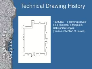
Lesson 1 In our modern world every item we use has a corresponding technical drawing somewhere. Because the idea is that anyone could read the technical drawings that is why it has standards and regulations. Before the computer era the precious plans were photographed to microfilm. Some of the regulations originate from that practice. Technical drawing in Photonics
Lesson 1 A0: 1 m2 and the sides are 1:√2 Standard drawing sizes (Europe) A0 A1 A2 A3 A4: 297 mm x 210 mm A4 Technical drawing in Photonics
Lesson 1 Standard linewidths 0.18 mm 0.25 mm 0.35 mm 0.5 mm 0.7 mm 1.0 mm 1.4 mm 2.0 mm On a single drawing only two sizes are allowed: a thin line and a thick line (which is exactly the double of the thin one). –This rule originates from the microfilm era. E.g.: 0.5 mm and 1.0 mm or 0.35 mm and 0.7 mm can be in pair. But: e.g. 0.35 mm and 0.25 mm are not allowed together. Technical drawing in Photonics
Lesson 1 Standard linetypes visible contour/edge invisible contour/edge invisible contour/edge almost for anything else ... symmetry line or trajectory plane or edge with special treatment trace of a section plane • outline of connecting parts • terminal position of a moving part • median • outline before shaping • outline of parts in front of a section plane Technical drawing in Photonics
Lesson 1 Drawing title area Drawing title area Drawing title area Every drawing have to have a drawing title area X-type set Y-type set Technical drawing in Photonics
Lesson 1 On a technical drawing a simple font is required. (e.g. Arial) • If drawing by hand: • the linewidth of a letter equals to the thin line (let us call it 1 unit), • the height of an ”a” is 7 units, • the height of a ”B” is 10 units, • the distance between two letters is 2 units, • the distance between two words is 6 units, • the distance between the baselines of two rows is 18 units. A lettering guide may also be used. Technical drawing in Photonics
Lesson 1 2.5 Dimensioning Every dimension must be given without explicitly placing the units. The unit is usually ”mm” or ”m”, but it may be ”mm” or ”km”, depending on the scale. The arrows at the end of the dimension line have a 15o angle and have a minimum length of 2.5 mm. Technical drawing in Photonics
Lesson 1 • References • Ocskó Gy., Seres F.: Gépipari szakrajz, Skandi-Wald Könyvkiadó, Budapest, 2004 • Lőrincz P., Petrich G.: Ábrázoló geometria, Nemzeti Tankönyvkiadó Rt., Budapest, 1998 • Pintér M.: AutoCAD tankönyv és példatár, ComputerBooks, Budapest, 2006 Technical drawing in Photonics