State Machine Design Procedure for Sequence Recognizer
Understand the problem specifications, formulation, state assignment, flip-flop input equation determination, output equation determination, optimization, technology mapping, and verification for a sequence recognizer state machine design. Follow a step-by-step procedure to design the state machine efficiently.

State Machine Design Procedure for Sequence Recognizer
E N D
Presentation Transcript
Sequential Circuit Design Section 5-5
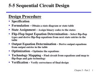
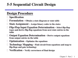
State Machines Design Procedure • Specification- obtain (produce) problem description • Formulation - Obtain a state diagram or state table • State Assignment - Assign binary codes to the states • Flip-Flop Input Equation Determination • Select flip-flop types • Derive equations of inputs to the flip-flops from next state entries in the table
State Machines Design Procedure (continued) • Output Equation Determination - Derive output equations from output entries in the table • Optimization -Optimize the equations • Technology Mapping – • Find circuit from equations • Map to flip-flops and gate technology • Verification - Verify correctness of final design
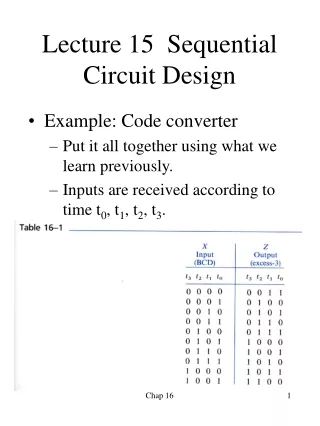
State Machines Design Procedure;Example: Sequence Recognizer Specification Example 5-3 (pp. 233-235) • Specification- obtain (produce) problem description • Circuit has input, X, and output, Z • Recognizes sequence 1101 on X • Specifically, if X has been 110 and next bit is 1, make Z high
Understand the problem specifications:Sequence Recognizer • Sequential machine recognizes the sequence 1101 • The sequence 1111101 contains 1101 • Sequential machine must remember that the first two one's have occurred as it receives another bit.
Understand the problem specifications:Sequence Recognizer II • Also, the sequence 1101101 contains 1101 as both an • initial subsequence 1101101 • final subsequence 1101101 • The sequence 1101 must be recognized each time it occurs in the input sequence.
State Machines Design Procedure;Example: Sequence Recognizer Formulation • Formulation - Obtain a state diagram or state table • States remember past history • Must remember we’ve seen 11 asmachinereceivesanotherbit • Must remember we’ve seen 110 when anotherbit comes along • There is more to remember…. • Tell me one necessary state
Beginning State • System starts in some state, A A
First 1 • If 1 appears, move to next state B • B recognizes (remembers) that 1 was received Input / Output
Second 1 • New state, C • C remembers that 11 was received
Next a 0 • If 110 has been received, go to D • D remembers that 110 was received • Next 1 will generate a 1 on output Z
What else? • What happens to arrow on right? • Must go to some state. • Where? • Remember we’ve just seen 01
You must cover every possibility • You must have every possibility out of every state • In this case, just two possibilities: X = 0 or 1 • We fill in other cases on the white board
Remembersthat {a single “1” sequence occurred } Remembersthat a {“110” sequence occurred} Remembersthat {a “11” sequence occurred } Fill in
Answer Remembers: No proper sub-sequence of the sequence 1101 has occurred
Recognize 1101 (continued) 1/0 0/0 1/0 A B C D 1/1 • The states have the following abstract meanings: • A: No proper sub-sequence of the sequence has occurred. • B: The sub-sequence 1 has occurred. • C: The sub-sequence 11 has occurred.
Example: Recognize 1101 (continued I) 1/0 0/0 1/0 A B C D 1/1 • D: The sub-sequence 110 has occurred. • The 1/1 on the arc from D to B means that the last 1 has occurred and thus, the sequence is recognized.
3. State Assignment • Each of the m states must be assigned a unique binary code • Sequence Recognizer: m=4 (A, B, C, D) • Minimum number of bits required is n such thatn ≥ log2mwhere x is the smallest integer ≥ x • In general, there can be 2n - m unused states
State Assignment for the Sequence Recognizer: Example 5-5 p. 239 Present Next State Output State x=0 x=1 x=0 x=1 A A B 0 0 B A C 0 0 C D C 0 0 D A B 0 1 • # of needed codes = m = 4; • How may assignments of codes are possible with 2 bits? • 4 3 2 1 = 24
State Assignment – (continued) • Let us choose the code assignment : A = 0 0 , B = 0 1 , C = 1 1 , D = 1 0 • The resulting coded state table:
4. Find Flip-Flop Input andOutput Equations X X X 0 0 0 0 1 0 DA 0 0 0 1 0 1 Z DB B B B 1 1 0 0 1 0 A A A 0 0 0 0 1 1 • Assume D flip-flops, outputs labeled A, B • Obtain K-maps for DA, DB, and Z:
6. Optimization: X X X 0 0 0 0 1 0 0 0 0 0 1 1 B B B 0 1 0 1 1 0 A A A 0 0 0 1 1 0 • Performing two-level optimization: DA = AB + XBDB = X Z = XAB DA Z DB
7. Map Technology A D C R Z B D X Clock C R Reset • DA = AB + XBDB = X Z = XAB • Initial Circuit:
Mapped Circuit - Final Result A D C R Z B D X C Clock R Reset Library: • D Flip-flopswith Reset • NAND gateswith up to 4inputs andinverters