Plans for Demonstrator Flip Chip Bonding
Plans for Demonstrator Flip Chip Bonding. General. Bump pad layout as in ALICE/ M edipix (see talk by Massimiliano ) Sensor wafers will be delivered as 4” wafers Demonstrator chips will be delivered as single dies Standard processing only possible for sensor wafers (full wafer processes)

Plans for Demonstrator Flip Chip Bonding
E N D
Presentation Transcript
General • Bump pad layout as in ALICE/Medipix (see talk by Massimiliano) • Sensor wafers will be delivered as 4” wafers • Demonstrator chips will be delivered as single dies • Standard processing only possible for sensor wafers (full wafer processes) • Need to develop a procedure for the demonstrator dies
{ www.fujitsu.com
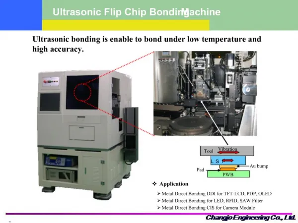
S. Savolainen-Pulli/VTT } • Dicing of the wafers • Flip chip bonding of a sensor to one (or more) readout chip and reflow
Bump Deposition • Simplified scheme • S. Savolainen-Pulli (Pixel 2005 conference) • In standard process done on wafer level How to deposit UBM and eventually Pb-Sn on single dies? Non-standard process!
Discussion with VTT • First meeting February 2008: VTT proposes to use reverse rework process (transfer Pb-Sn bumps to the dies from a carrier wafer) • Continuing discussion: • How to deposit the wettable metal which is underneath the Pb-Sn on the ROC? • How to protect the wire bonding pads? • Could the Pb-Sn be skipped on the ROC side at all?
Status • Discussion on technical matters with VTT (4/12/08), i.e. proposal to suppress Pb-Sn on ROC • Proposed tentative workplan to have process ready by April when all components will be available • Process development will be done in the coming months using dummies • Order for demonstrator being prepared • Target: 10+10 bonded chips before summer