Flip Chip Technology Lane Ryan
120 likes | 840 Vues
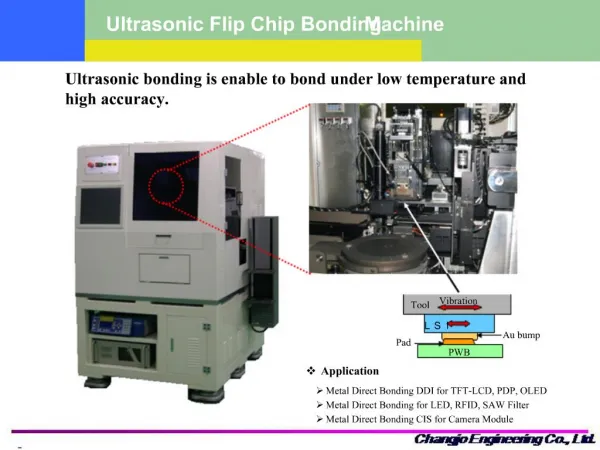
Flip Chip Technology Lane Ryan. Packaging Options. This presentation is going to focus on the advantages of the flip-chip method compared to wire bonding. Manufacturing Process. IC’s created on the wafer Solder bumps are deposited on metalized pads on the chip surface

Flip Chip Technology Lane Ryan
E N D
Presentation Transcript
Packaging Options This presentation is going to focus on the advantages of the flip-chip method compared to wire bonding.
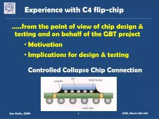
Manufacturing Process • IC’s created on the wafer • Solder bumps are deposited on metalized pads on the chip surface • Chips are then flipped so that the solder bumps are touching the external circuitry • Solder bumps are bonded to the connectors • Insulating adhesive (underfill) is injected in the small space between the chip and the underlying mounting.
Flip Chip Advantages/Disadvantages • Advantages • Increased signal speed • Reduced inductance (compared to wire bonding) • Better thermal performance (in some cases) • Miniaturization • Disadvantages • Difficult to troubleshoot • Difficult to remove or manually install • Mechanical issues
Comparison • Wire-bonding interconnection inside the ADF7020 chip packaging vs. flip chip [1]
Underfill • Technology is driving smaller bump pitch, bump diameter, and gap height. This creates challenges for injecting the underfill. [3] • Small spaces affect the flow of the underfill material. • Maximum underfill particle size should be less than one third of the gap height between the chip and substrate. This plays an important role in CTE. • Underfill is used to reduce the impact of global mismatch in thermal expansion. • Lower CTE underfill can decrease solder fatigue considerably.
References • [1] L. Zheng, K. Rodgers, A. Mathewson, and B. O’Flynn, “A simulation-based design method to transfer surface mount RF system to flip-chip die implementation,” Electronic System-Integration Technology Conference, Berlin, Germany, pp. 1-5, Sept. 2010 • [2] G. Baumann, D. Ferling, and H. Richter, “Comparison of flip chip and wire bond interconnections and the technology evaluation on 51 GHz transceiver modules,” 26th European Microwave Conference, Prague, Czech Republic, pp. 98-100, Sept. 1996 • [3] T. Chen, J. Wang, and D. Lu, “Emerging Challenges of Underfill for Flip Chip Application,” Electronic Components and Technology Conference, pp. 175-179 Vol. 1, June 2004