Download
1 / 1
20 likes | 205 Vues
Low Density Parity Check Code Implementation Zachary Saigh & Matthew Pregara Faculty advisors: Drs. In Soo Ahn and Yufeng Lu Department of Electrical and Computer Engineering. LDPC Codes. Motivation. Simulation Results.

E N D
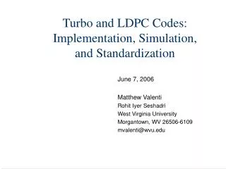
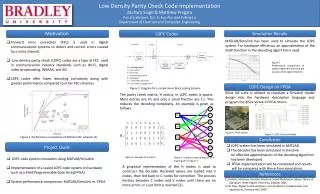
Low Density Parity Check Code Implementation Zachary Saigh & Matthew Pregara Faculty advisors: Drs. In Soo Ahn and Yufeng Lu Department of Electrical and Computer Engineering LDPC Codes Motivation Simulation Results MATLAB/Simulink has been used to simulate the LDPC system. For hardware efficiency, an approximation of the math function in the decoding algorithm is used. • Forward error correction (FEC) is used in digital communications systems to detect and correct errors caused by a noisy channel. • Low density parity check (LDPC) codes are a type of FEC used in communication industry standards such as Wi-Fi, digital video broadcasting, WiMAX, and 4G. • LDPC codes offer lower decoding complexity along with greater performance compared to other FEC schemes. Figure 5. Performance comparison of original algorithm and multiple accuracy level approximations LDPC Design on FPGA Figure 2. Diagram for a simple linear block coding Scheme Xilinx ISE suite is utilized to translate a Simulink model design into the hardware description language and program the Xilinx Virtex-II FPGA device. The parity check matrix, H matrix, in LDPC codes is sparse. Most entries are 0’s and only a small fraction are 1’s. This reduces the decoding complexity. An example is given as follows. Figure 6. FPGA device Figure 7. LDPC Simulink Model Figure 1. Performance comparison of different FEC schemes [1] Conclusion Project Goals • LDPC system has been simulated in MATLAB. • The decoder has been simulated in Simulink • An effective approximation of the decoding algorithm • has been developed • FPGA implementation will be completed and results • will be compared with those from simulations Figure 3. Example of H matrix Figure 4. Graphical representation of H matrix given in Figure 3. • LDPC code system simulation using MATLAB/Simulink • Implementation of a scaled LDPC code system on hardware • such as a Field Programmable Gate Array(FPGA) • System performance comparison: MATLAB/Simulink vs. FPGA A graphical representation of the H matrix is used to construct the decoder. Received values are loaded into V nodes, then fed back to C nodes for correction. The process iterates between C nodes and V nodes until there are no more errors or a set limit is reached [2]. References [1] Valenti, Matthew. Iterative Solutions Coded Modulation Library Theory of Operation. West Virginia University, October 2005. [2] B. Sklar, Digital Communications, second edition: Fundamentals and Applications, Prentice-Hall, 2000.