
Exploring First Order RL and RC Circuits
E N D
Presentation Transcript
Transient Circuits Chapter 7 RL and RC first order circuits
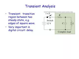
First Order RL and RC circuits • L and C components have the ability to store energy in magnetic or electric fields • Circuits that have only 1 L or 1 C have a first order response to a sudden influx or release of the energy. • When the energy is suddenly released, the response is called the natural response. • When the energy is suddenly supplied, to the circuit, it is called the step response. • Since there is only 1 element with a differential characteristic the differential equation is first order.
RL circuit • A switch is drawn as: • Depending on the circuit it either opens or closes to release charge. • Assume a switch is closed/open until the circuit is settled to its eventual steady state. Then it is instantly changed and the charge moves.
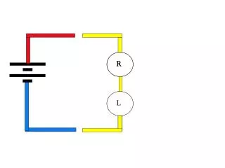
Circuit Natural Response • If a circuit with an inductor is fully charged for a long time and then the charge is suddenly released the circuit response is called the natural response. • The charge dissipates in the resistance of the circuit and decays exponentially to 0. • For example if the circuit shown is charged for a long time prior to t=0, then the switch is open. The natural response as the stored charge flows in R • Write a circuit equation around the loop on the right.
Natural Response • To solve the equation, separate the variables and Integrate both sides. Then the response is i(t) is a decaying exponential.
Voltage at t = 0 • The voltage at t=0 undergoes an instantaneous change. • Just before we release the switch the inductor voltage (due to no change in current) at t=0- is 0 • Once the switch is closed and the circuit releases the energy (natural response) the current is changing the voltage at t= 0+ is v= I0R • The voltage at exactly t = 0 is unknown. • The voltage is also a decaying exponential over time.
Power in the RL circuit • The power can be expressed in a variety of ways. • The power in the resistor is: • The energy delivered to the resistor after the switch is thrown is: • The second term goes to 0 as t gets larger. • Energy is:
Time constant for the RL circuit • The time constant term is the reciprocal of the coefficient of t in the exponential term. • The term: relates how the current or voltage falls off as a function of time. • The coefficient of t: is the rate at which it falls off. • The reciprocal of this term is called the time constant, =
Elapsed time vs. fraction of initial value Note after ~5 the response is down to .0067 of initial max
Assessment Problem 7.1a. • What is the initial value of I at t=0+:
Assessment Problem 7.1a. • “Thevenize” around the inductor. • Use Source transformations from left side and simplify to inductor: • Transform 120V to a 40 A in parallel with 3 • Resistors 3 || 30 becomes 2.73 • Another source transformation 109.1V in series with 2.73 • Add the 6 becomes 8.73 in series with 109.1V • a last source transformation leaves 12.5 A current source • And resistors in parallel 8.73 and 2 1.6 • With the inductor now the initial inductor current is 12.5 A
Assessment Problem 7.1a.
Capacitor Natural Response • Similar to the inductor circuit we charge up the capacitor, • Instead of soring the energy in magnetic flux, the capacitor stores energy in electric flux. • The capacitor voltage is stored until a path for he current allow the charge to dissipate. When the capacitor is fully charged it appears as an open circuit, stopping the flow of current until the switch is thrown at time t=0. • Vg appears across the capacitor at t=0- • When the switch is thrown at t=0+ the capacitor starts at Vg and dissipates through the resistor R to 0 V. • The time characteristic is exponential similar to the inductor but the time constant is dependent on R and C.
Analysis for the natural response of C • Write a loop equation • Use the same techniques for voltage in C as was used for current in L previously • integrate both sides
Natural response of the Capacitor • We have the result for voltage response • V(0) = Vg in this case • Now the time consent is = RC • Now we can devise an expression for current, power and energy
Current, Power and Energy current power energy = at t= 0
Assessment Problem 7.3 • Use source transformations to reduce the LHS up to the capacitor • Initial value of v(t) = ~200V • After the switch is open and the current stored in the capacitor flows through the 50K resistor • time constant is RC =50K*0.4u=20ms
Assessment Problem 7.3 • Use source transformations as follows --> --> --> --> --> -->
Step Response - Inductor • A full discharged inductor (L) or Capacitor (C) when subjected to an initial infusion of charge reacts to the sudden change with a “step response” • Take the inductor first: initially i=0 then the switch is closed at t=0 and current flows: the loop equation rearranging the termsnow multiply both side by dtseparate the variables Then integrate both sides
Completing the integration • The LHS has the form: • Where a=1 b= - • So the LHS integral becomes: • And the RHS is just • now raise both sides by e
Completing the formula • Now solve for i(t): • If initial energy in the inductor is 0 this reduces to
Step response of inductor current As t -> -> 0 and the final value ->
Voltage across the inductor • multiply by L and –R • VL falls from Vs exponentially
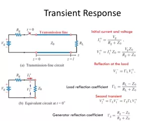
Spice solution • Prior to t=0, I 12A • After t= 0 switch in position a. The voltage across resistor is -80V
After switch ia closed • .icis initial condition for inductor current I(L1) which yields 200V at V2 • (8+12)A*10 =200V • .tranis transient or time simulation
Plot of voltage: at V2 starts at -200V-> 0current IL: starts at 12A and decays to-8 A
Step response of a capacitor first order circuit • Before t=0 the switch is open the node at top is : v=is R • When the switch is closed at t=0 the node equation becomes: v
Capacitive Step Response • Integrate both sides a=-1 b= RIs
Assessment Problem 7.6 • From example 7.6 vo and i0 are determined to be: • Both equations are valid after the switch is thrown to 2.
Assessment Problem 7.6 • Using these values already determined find the Voltage across the160 resistor: note current through the 8K resistor causes the polarity to be as shown v8K + - v1
General Solution • You can see that both inductor and capacitor single order system exhibit the same behavior. • For natural the stored energy is released in a exponential decay from a stored value. • For step response the energy accumulates to the maximum value in an exponential • The response curves are similar and depend on the time constant of the circuit. • For inductor circuit: • For capacitor circuit:
Simulation and lab • In the lab we use a square wave to mimic switch we can also simulate the same thing in spice. • Voltage source can be implemented as a pulse generator • Pulse(V1 V2 TdelayTriseTfall Ton TperiodNcycles) • Pulse can be specified as 0 to 5 V with rise abd fall tiems of .001us ata value of 5V for 500u and repeating ever 1000u number of cycles =2 • Which is ~ 5 time constants for the circuit • How would you extend it to 10 time constants?
Chapter 8 RLC circuits
RLC circuits • Two energy conserving components lead to second order systems. • Two configurations • Parallel • Series • Look at the second order systems in general: • The system has a solution of the form • Where x is a variable representing either v or I depending on the topology. • A represents the max stored value • S represents the time constant ( or rate of the decay)
Parallel RLC circuit • The common variable here is v so we write the sum of currents in terms of v • Now we have a second order differential equation We can use the techniques of differential equations to solve.
Solution to second order equation • Assuming v has the form: : we substitute v in the equation and after differentiating the appropriate terms we get: • Factoring out the common exponential term: • Of the three terms • if A=0 the solution would be trivial • cannot be 0 • This quadratic can take on 3 cases depending on the values
Characteristic equation • The form of: is the general form of the quadratic equation. • The roots are: • The discriminant : suggests the type of solution • > 0 indicated 2 distinct roots • = 0 duplicate roots • < 0 complex conjugate roots
Using the discriminant to suggest the solution • a=1 b= ,c= • compared to 0 • Now we introduce an alternative variables, and ω0 • The roots can be specified in terms of these:
Alternative variables for the parallel circuit • Neper Frequency: • Resonant radian frequency: • overdamped: real distinct roots • underdamped: complex roots • critically damped: repeated real roots
Assessment 8.1 a. • If R= 100 and L= 20mH what value of C will make the system critically damped? • Criteria for critically damped: • Thus: • Rearranging lets us write
Assessment 8.1 b. • If C is adjusted to give =5 K rad/sec what is the value of C and the roots of the equation (form of solution) • = 5K => C=1uF
Form of solutions for the 3 cases • Real distinct roots: • To solve this the following steps are necessary: • Find the roots of the characteristic equation. • Find v(0+) and using circuit analysis • Find the values of and solving : • Substitute the values into the equation for the solution above.
Finding the solutions • Underdamped solution: • Put the roots of the characteristic equation in the form of: • Where the damped radian frequency. • now factor out the term and we have the exponential form of the sine expanding each ej using euler’s identity we have
Underdamped solution • Determine the coefficients B1 and B2 by the initial energy stored in the system by evaluating the voltage and its derivative at t=0+ • V(0+)=V0 = • The underdamped solution describes a decaying oscillation as shown also known as “ringing”.
Assessment problem 8.4 • A 10mH inductor and 1uF capacitor are connected with a resistor R. The roots of the characteristic equation are: -8000+j6000 and -8000-j6000 V(t=0)=10V iL(t=0)=80mA • a. What is R? • b. dv(0)/dt?
Assessment 8.4: 10mH inductor and 1uF • Roots of Characteristic equation are complex conjugates : • -8000+j6000 and -8000-j6000 • Has the form • Plug in 0 in the equation for v(t): V(0)=B1 • Part a. = 8000 = • iL(0+)=80m and VC (0+)=10V • V(0+)=V0V =