POAD Book: Chapter 10 POAD: The Design Refinement Phase
This lecture by Dr. Hany H. Ammar provides an in-depth exploration of the Design Refinement Phase in the Pattern-Oriented Analysis and Design (POAD) process. It focuses on three main activities: instantiating pattern internals, developing class diagrams, and optimizing designs. Key concepts include specialization, concrete instantiation of patterns, and relationship declaration among pattern interfaces. The session emphasizes the transition from generic designs to application-specific implementations, ensuring efficient design optimization and traceability throughout the modeling process.

POAD Book: Chapter 10 POAD: The Design Refinement Phase
E N D
Presentation Transcript
POAD Book: Chapter 10POAD: The Design Refinement Phase Instructor: Dr. Hany H. Ammar Dept. of Computer Science and Electrical Engineering, WVU
Outline • Review of POAD Process • This lecture focuses on the design refinement phase. • This phase has 3 main activities • Instantiating the pattern internals • Developing class diagrams, • Optimizing the design
Application Requirements Requirement Analysis Required Conceptual Components Acquaintance Pattern Library Retrieval Selection Analysis Candidate Patterns Selected Patterns Design Design Refinement Create Pattern Instances Selected Patterns Define Pattern Relationships Constructing Pattern-Level models Construct Pattern-Level Diagrams Pattern-Level Diagrams Declare Pattern Interfaces Constructing models for Pattern-Level with Interfaces Identify Relationships between Pattern Interfaces Pattern-Level with Interfaces Diagrams Constructing models for Detailed Pattern-Level Detailed Pattern-Level Diagrams (c) Design The POAD process a) overall phases, b) analysis, c) design, and d) design refinement (b) Analysis (a)Overall POAD Detailed Pattern-Level Diagrams (d) Design Refinement Concretization Instantiating Pattern Internals Specialization Domain Specific Detailed Pattern-Level Diagrams Develop Class Diagrams Initial UML class diagram Reduction Design Optimization Merging & Grouping Optimized class diagram
Detailed Pattern-Level Diagrams Concretization Instantiating Pattern Internals Specialization Domain Specific Detailed Pattern-Level Diagrams The Design Refinement phase. Develop Class Diagrams Initial UML class diagram Reduction Design Optimization Merging & Grouping Optimized class diagram
Instantiating Pattern Internals • Purpose- to create an application-specific instances of the patterns used in the Design phase • Process- instantiation process involves describing the patterns and their constituents in an application specific context • Instantiation is 2 parts; first part defining a pattern instant and its interfaces as preformed in the previous phase, the second part of pattern internals is the subject of this phase.
Instantiating Pattern Internals • Specialization (generic -> application specific) • The pattern’s Class diagram is very general, not application specific. • During Design-refinement, the generic design is specialized, specialization includes: renaming classes, methods and relationships, and adding domain specific details
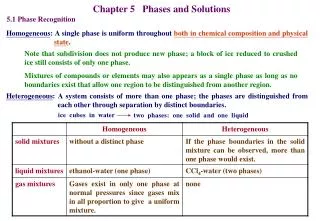
Instantiating Pattern Internals • Specialization cont’d • Renaming pattern internals involve. • Revealing the internal class diagram model for each pattern instance. • Renaming the internal classes of each insatnce according to the application design environment. • Giving application specific names for the methods/operations in each pattern class. • Example, feedback control system, readings from plant are processed then compared to user input
Instantiating Pattern Internals • difference between processed readings (feedback data) and preset input is used to trigger a control action • Designer uses ErrorObserver instance of type observer to monitor feedback data. • Abstract subject is the abstract interface for the component observed. The concrete subject represents the implementation of the abstract interface, therefore the ConcreteSubject is named FeedbackSubject as shown in the next slide
<<Observer>> <<Observer>> ErrorObserver ErrorObserver Subject Subject Observer Observer Attach() Attach() Update() Detach() Update() Detach() Notify() Notify() FeedbackSubject ConcreteSubject ErrorObserver ConcreteObserver Notify subjectState subjectState observerState observerState getState() getState() Update() Update() After specialization Before specialization
Instantiating Pattern Internals • Instantiation through subclassing and realization • The class diagram for any pattern contains abstract classes and concrete classes. The abstract classes my only be interfaces or they could have implemented, default functions, etc. • During instantiation designer determines which abstract classes will be implemented, and the concrete subclasses needed. • Instantiation through realization. • When abstract class is pure, the implementation class that realizes the interface is defined
Instantiating Pattern Internals • Instantiation by subclassing • When the abstract class has default implementation, the designer defines an implementation and determines which methods to use and which methods to override. • Keeping History of Participants’ Names • The underlying models should keep track of the name changes. • History tracking enables traceability between models.
Instantiating Pattern Internals • Concretization- bringing abstract design to a more concrete form • Concretization is different from specialization. • During concretization abstract designs are turned into concrete ones by selecting among design alternatives • Scope- We have shifted out focus from design of the overall application to the internals of each pattern
Instantiating Pattern Internals • Product- The application-specific Detailed Pattern-Level design Diagrams. • The following slides will show the patterns for the feedback control system instantiated
<<Strategy>> FeedforwardStrategy (from POAD1-Feedback) AbstractController Controller AlgorithmInterface() ContextInterface() Controller ConcreteStrategyA ConcreteStrategyB AlgorithmInterface() AlgorithmInterface() Instantiating the FeedforwardStrategy pattern
<<Observer>> ErrorObserver (from POAD1-Feedback) AbstractSubject AbstractObserver Attach() Update() Detach() n n Notify() Notify Update FeedbackSu ErrorObserver bject observerState subjectState Update() GetState() Instantiating the ErrorObserver pattern
<<Observer>> FeedbackObserver (from POAD1-Feedback) AbstractSubject AbstractObserver Attach() Update() Detach() n n Notify() Update Notify FeedbackObs Measurement erver Subject observerState subjectState Update() GetState() Instantiating theFeedbackObserver pattern
<<Blackboard>> Blackboard (from POAD1-Feedback) Blackboard setData DataHolder setData() n n getData() getData ErrorData MeasuredData FeedbackData Instantiating theBlackboard pattern
<<Strategy>> FeedbackStrategy (from POAD1-Feedback) Feedback FBAbstractController ContextInterface() AlgorithmInterface() Feedback FBConcreteStrategy FBConcreteStrategy A B AlgorithmInterface() AlgorithmInterface() Instantiating the FeedbackStrategy pattern
Detailed Pattern-Level Diagrams Concretization Instantiating Pattern Internals Specialization Domain Specific Detailed Pattern-Level Diagrams The Design Refinement phase. Develop Class Diagrams Initial UML class diagram Reduction Design Optimization Merging & Grouping Optimized class diagram
Developing Initial Class diagram • Purpose – To develop a class diagram of the application using the class diagrams of the pattern instances • Process – We will use the diagrams from the previous phase, the pattern interfaces and instantiated details of the pattern internals to generate a UML class diagram.
Developing Initial Class diagram • Revealing the Instantiated Pattern Internals • Previously the application-specific pattern instances were developed. • The classes and methods have application specific names and can thus be used as the basis for the initial class diagram. • Tracing Pattern Interfaces to internal Realization • Previously we determined the relationships between pattern internals • Now, we are tracing each interface to the internal pattern participant that implements it
? <<Type>> PatternInstance1 ? <<Type>> PatternInstance2 Interface 1 ? Interface 2 Developing Initial Class diagram • The following diagram shows this step tracing each interface to the internal pattern participant that implements it
Developing Initial Class diagram • Each interface is realized by an internal participant, this means that the interface can be traced back to the element implementing or defining it using a UML realization • Consider FeedforwardStrategy and the ErrorObserver Pattern discussed previously, the following diagram shows there interfaces and the elements that implement them
<<Strategy>> FeedforwardStrategy AbstractController Controller Context AlgorithmInterface() ContextInterface() ConcreteStrategyA ConcreteStrategyB AlgorithmInterface() AlgorithmInterface() <<Observer>> ErrorObserver Subject Observer Attach() Detach() Update() n n Notify() Notify Update() ErrorObserver FeedbackSubject observerState subjectState Update() GetState()
Developing Initial Class diagram • Tracing the Relationship between pattern instances • Using the relationship between interface and the traceability between interface and pattern internal the designer establishes relationship between internals of the 2 pattern instances. • Interfaces can be interface operations or methods; there are several relationships • Class/Class • Class/Operation • Operation/Operation • After All tracing and realization we get a class diagram
AbstractController Controller AlgorithmInterface() ContextInterface() ConcreteStrategyA ConcreteStrategyB AlgorithmInterface() AlgorithmInterface() Subject Observer Attach() Update() Detach() n n Notify() FeedbackSubject ErrorObserver observerState subjectState Update() GetState()
Developing Initial Class diagram • Product – The initial UML class diagram for the application design
AbstractSubject AbstractObserver Attach() Update() Detach() n n AbstractController Controller Notify() AlgorithmInterface() ContextInterface() FeedbackObserver MeasurementSubject observerState subjectState ConcreteStrategyA ConcreteStrategyB Update() GetState() AlgorithmInterface() AlgorithmInterface() AbstractSubject AbstractObserver FBAbstractController Attach() Feedback Update() Detach() n n Notify() AlgorithmInterface() ContextInterface() ErrorObserver FeedbackSubject FBConcreteStrategyA FBConcreteStrategyB observerState subjectState AlgorithmInterface() AlgorithmInterface() Update() GetState() Blackboard DataHolder setData() n n getData() ErrorData MeasuredData FeedbackData Initial Class Diagram Feedback Control System
Detailed Pattern-Level Diagrams Concretization Instantiating Pattern Internals Specialization Domain Specific Detailed Pattern-Level Diagrams The Design Refinement phase. Develop Class Diagrams Initial UML class diagram Reduction Design Optimization Merging & Grouping Optimized class diagram
Design Optimization • Purpose – To optimize the class diagram, and prepare it for implementation. • Process – We use Reduction, merging and grouping to optimize the class diagram. • Reduction – Consider a scenario where we have multiple instances of the same type • Multiple instances indicate multiple abstract class
Design Optimization • The abstract class is seldom implemented, it is as source for subclassing and realization. • Reduction is the process where the replicated abstract class is removed. • The two classes must be similar • In the case of interfaces the common interface class has to provide the same interface signature
<<Observer>> <<Observer>> SensorObserver ErrorObserver Subject Subject Observer Attach() Observer Attach() Update() Detach() Update() Detach() Notify() Notify() SensorSubject FeedbackSubject FeedbackObserver subjectState ErrorObserver subjectState observerState observerState getState() getState() Update() Update() (b) (a)
Subject Observer Attach() Detach() Update() Notify() SensorSubject FeedbackObserver subjectState observerState getState() Update() FeedbackSubject ErrorObserver subjectState observerState getState() Update() (c)
Design Optimization • In the case of the abstract class • The common classes must provide same interface, and default implementation. • Merging and Grouping – Sometimes patterns contain classes with trivial responsibilities • Some classes just forward a message to another class • These classes should carry other functionality in the application besides the functionality that they provide.
Design Optimization • See the Strategy pattern; the Context class is only the interface, thus the context class would have to play additional roles in the application design (See Figure in Next slide). • Instead of using one class for trivial tasks, designer might consider merging classes from more than one pattern instance • 2 important steps to remember in merging • identifying which classes to merge • defining how to merge the classes
<<Strategy>> FeedforwardStrategy Strategy Context AlgorithmInterface() ContextInterface() Context ConcreteStrategyA ConcreteStrategyB AlgorithmInterface() AlgorithmInterface()
Design Optimization • Identifying which classes means the designer must study the pattern internals and the relationships between instances, The pattern internal design and pattern documentation can indicate which classes are candidates for merging. • Another method for determining merge candidates is by studying the pattern relationships. • Relationships are between 2 pattern participants, these 2 participants are candidates for merging
Design Optimization • POAD uses Hard merge. • Hard merge - designer merges the two classes to produce one class that has no conflicting methods and attributes • When we merge two classes that have no class relationship between them, the new class will have relationships with other application classes
Design Optimization • When we merge two classes that have an association relationship, the association between the two original classes is retained in the merged class as calls between internal class methods • Consider the merging activity in the Feedback control application
Subject Observer Attach() Update() Detach() n n Notify() FeedbackSubject ErrorObserverController AbstractController observerState subjectState AlgorithmInterface() ContextInterface() Update() GetState() The ErrorObserver is merged with the context Class of the Strategy pattern ConcreteStrategyB ConcreteStrategyA AlgorithmInterface() AlgorithmInterface()
Design Optimization • Product - An optimized class diagram for the application, which is more dense and more profound
Controller AbstractController ContextInterface() AlgorithmInterface() ConcreteStrategyA ConcreteStrategyB FBConcreteStrategyA FBConcreteStrategyB AlgorithmInterface() AlgorithmInterface() AlgorithmInterface() AlgorithmInterface() AbstractSubject AbstractObserver Attach() Update() Detach() n n Notify() FeedbackSubjectObserver ErrorObserver MeasurementSubject observerState subjectState Update() GetState() Blackboard DataHolder setData() n n getData() MeasuredData FeedbackData ErrorData Refined Class Diagram for feedback control system (case study 1)
F_controller : AbstractController Strategy1 : ControlStrategyA 1: Apply (DataHolder*) 15: Control (DataHolder*) 13: Analyze() FB_Strategy : FBControlStrategyA 2: Notify ( ) 12: GetInput() 5: MeasurePlant ( ) 7: FBApply () 9: Notify() 3: Update ( ) 10: Update() Feedback : FeedbackSubjectObserver Error : ErrorObserver Measurement : MeasurementSubject 4: GetState ( ) 11: Getstate() 8: Update () TheBlackboard: Blackboard 14: Update () 6: Update () The Feedback Control Example Object Collaboration Diagram