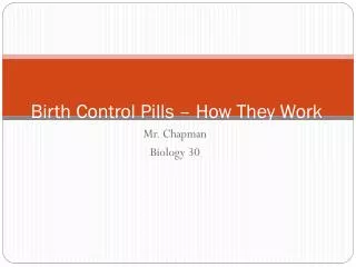
Processor Data Path and Control How they work together
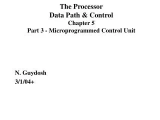
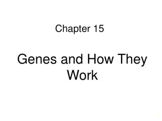
Processor Data Path and Control How they work together. MEMORY MAR MDR. PROCESSING UNIT ALU TEMP. CONTROL UNIT PC IR. Von Neumann Model. INPUT Keyboard Mouse Scanner Disk. OUTPUT Monitor

Processor Data Path and Control How they work together
E N D
Presentation Transcript
MEMORY MAR MDR PROCESSING UNIT ALU TEMP CONTROL UNIT PC IR Von Neumann Model INPUT Keyboard Mouse Scanner Disk OUTPUT Monitor Printer LED Disk
CONTROL UNIT Processor Example - Von Neumann Model
CONTROL UNIT Data Path The data path of a computer is all the logic used to process information Filled arrow = info to be processed. Unfilled arrow = control signal.
One More Device • Tri-state buffer • NOT an inverter! • Device with a special output that can take a third state (i.e. besides 0 and 1) • Allows wires to be “shared” • Alternative to mux • Only one source may drive at a time! • Usually used to control data over a bus D Q E Z = “high impedance” state
Data Path Components • Global bus • Set of wires that carry 16-bit signals to many components • Inputs to bus are controlled by triangle structure called tri-state devices • Place signal on bus when enabled • Only one (16-bit) signal should be enabled at a time • Control unit decides which signal “drives” the bus • Any number of components can read bus • Register only captures bus data if write-enabled by the control unit • Memory and I/O • Control signals and data registers for memory and I/O devices • Memory: Memory Address Register (MAR), Memory Data RegisterMDR (also control signal for read/write) • Input (keyboard): KBSR, KBDR • Output (text display): DSR, DDR
CONTROL UNIT Data Path Filled arrow = info to be processed. Unfilled arrow = control signal.
Data Path Components • ALU • Input: register file or sign-extended bits from IR (immediate field) • Output: bus; used by… • Condition code registers • Register file • Memory and I/O registers • Register File • Two read addresses, one write address (3 bits each) • Input: 16 bits from bus • Result of ALU operation or memory (or I/O) read • Outputs: two 16-bit • Used by ALU, PC, memory address • Data for store instructions passes through ALU
Data Path Components • PC and PCMUX • Three inputs to PC, controlled by PCMUX • Current PC plus 1 (normal operation) • Adder output (BR, JMP, …) • Bus (TRAP) MAR and MARMUX • Some inputs to MAR, controlled by MARMUX • Zero-extended IR[7:0] (used for TRAP; more later) • Adder output (LD, ST, …)
Data Path Components • Condition Code Logic • Looks at value (from ALU) on bus and generates N, Z, P signals • N,Z,P Registers are set only when control unit enables them • Control Unit • For each stage in instruction processing decides: • Who drives the bus? • Which registers are write enabled? • Which operation should ALU perform? Lets Look at Instruction Processing next..
Instructions • Fundamental unit of work • Constituents • Opcode: operation to be performed • Operands: data/locations to be used for operation • Encoded as a sequence of bits (just like data!) • Sometimes have a fixed length (e.g., 16 or 32 bits) • Atomic: operation is either executed completely, or not at all
FETCH instruction from mem. DECODE instruction EVALUATE ADDRESS FETCH OPERANDS EXECUTE operation STORE result Instruction Processing
Instruction Processing: FETCH • Idea • Put next instruction in IR & increment PC • Steps • Load contents of PC into Memory Address Register (MAR) • Increment PC • Send “read” signal to memory • Read contents of Memory Data Register (MDR), store in IR F D EA OP EX S
CONTROL UNIT FETCH Example Control Load PC into MAR (inc PC) Data
CONTROL UNIT FETCH Example Control Load PC into MAR Data Read Memory
CONTROL UNIT FETCH Example Control Load PC into MAR Data Read Memory Copy MDR into IR
Instruction Processing: DECODE • Identify opcode • Usually the first four bits of instruction • 4-to-16 decoder asserts control line correspondingto desired opcode • Identify operands from the remaining bits • Depends on opcodee.g., for LDR, last six bits give offsete.g., for ADD, last three bits name source operand #2 F D EA OP EX S
CONTROL UNIT DECODE Decoding usually a part of the Control Unit but can be separate
Instruction Processing: EVALUATE ADDRESS • Compute address • For loads and stores • For control-flow instructions • Examples • Add offset to base register (as in LDR) • Add offset to PC (as in LD and BR) F D EA OP EX S
CONTROL UNIT EVALUATE ADDRESS Load/Store
Instruction Processing: FETCH OPERANDS • Get source operands for operation • Examples • Read data from register file (ADD) • Load data from memory (LDR) F D EA OP EX S
CONTROL UNIT FETCH OPERANDS ADD
CONTROL UNIT FETCH OPERANDS LDR
Instruction Processing: EXECUTE • Actually perform operation • Examples • Send operands to ALU and assert ADD signal • Do nothing (e.g., for loads and stores) F D EA OP EX S
CONTROL UNIT EXECUTE ADD
Instruction Processing: STORE • Write results to destination • Register or memory • Examples • Result of ADD is placed in destination reg. • Result of load instruction placed in destination reg. • For store instruction, place data in memory • Set MDR • Assert WRITE signal to memory F D EA OP EX S
CONTROL UNIT STORE ADD
CONTROL UNIT STORE LDR
CONTROL UNIT STORE • STORE • Set MDR
CONTROL UNIT STORE • STORE • Set MDR • Assert “write”
Time to Complete One Instruction • It takes fixed number of clock ticks (repetition of rising or falling edge) to execute each instruction • The time interval between ticks is known as clock cycle • Thus instruction performance is measured in clock cycles • Hence the clock sequences each phase of an instruction by raising the right signals as the right time • So what determines the time between ticks i.e. the length of the clock cycle?
Clocking Methodology • Defines when signals can be read and when they can be written • It is important to specify the timing of reads and writes because, if a value is written at the same time it is read, the value of read could be old, new or mix of both • All values are stored on clock edge (edge-triggered) i.e. within a defined interval of time (length of the clock cycle) • In a processor, since only memory elements can store values this means that • Any collection of combinational logic must have its inputs coming from a set of memory elements and its outputs written into a set of memory elements
Clocking Methodology • The length of the clock cycle is determined as follows: • The time necessary for the signals to reach memory element 2 defines the length of the clock cycle • i.e. minimum clock cycle time must be at least as great as the maximum propagation delay of the circuit
How does the control unit work ? • Two approaches: • Hardwired Control • Micro-programmed Control
Approach I: Hardwired Control • Hardwired Control • Directly connects the control lines to actual machine instructions • The instructions are divided into fields, and bits in the fields are connected to input lines that drives the various digital logic components • The control signals are some combination of the instruction bit plus other signals such as interrupts, or condition codes from previous instruction
Hardwired Control Implementation Decoder The Control Signals (red colored lines) are outputs by some combination of inputs from the instruction bit fields
ADD Instruction
Sequencing the Stages in Hardwired Implementation • The combination Control Unit set all the control lines needed by an instruction • How do we ensure that we sequence through Instruction cycle i.e. F->D->EA->OP->EX->S? • We connect the clock to a synchronous counter and the counter to the decoder • The decoder output enabled is based on counter outputs (i.e. which cycle you are in) • The decoder output is then used as enable signal (gating) to enable only certain control signals during a particular cycle • Note: the diagram does not show sequencing logic to avoid cluttering the diagram
Sequencing Instruction Stages in Hardwired Implementation • Example: • Suppose the max. number of cycles an instruction takes is 8 • Then we would have 3-bit counter whose outputs are fed into 3 x 8 decoder • The output of the decoder, T0 to T7 are enable based on count i.e. • T0 = 1 when count = 000 (cycle 0), all others are disabled … • T7 = 1 when count = 111(cycle 7), all others are disabled • The decoder output that is enabled used to define the behavior in a particular cycle • If < 8 clock cycles are required by another instr., then the counter is reset back to 0 (so the next instruction can properly function as well)
JMP Instruction
LDR Instruction DR BaseR
TRAP
Implementation Diagram is not complete • What about AND? NOT? BR? What changes would you make?
Approach II: Micro-programmed Control • In micro-programmed control, each machine instruction is in turn implemented by a series of microinstructions • Machine instructions are the input for a micro-program that converts the 1s and 0s of an instruction into control signals • The microinstructions are often stored in firmware or read only memory, which is also called the control store • Micro-program is also known as Microcode in some literature • Micro-program Control is essentially a Finite State Machine
Micro-programmed Control is a FSM State Machine Inputs Outputs Combinational Logic Circuit Control signals PC,IR, etc.. Next state Current state Storage Elements State
Micro-programmed Control: State Diagram • Finite state machine • Input: PC, IR, etc.. • Output: many control signals • Need to map abstract ops to control signals • E.g., MAR <- PC GatePC and LD.MAR • E.g., PC <- PC + 1 PCMUX=2 and LD.PC • If in state 1, then the micro- • Instruction for state 1 will encode information for GatePC, LD.MAR, PCMUX, LD.PC and next state as state 2
Implemented using Micro-program Control • The behavior during a given clock cycle is completely described by the 49 bit microinstruction • 39 control signals to assert datapath components • 10 signals + 9 other to determine the control signals for the next clock cycle • Each phase of instruction cycle may require more than one microinstruction • Hence a microinstruction is retrieved during each clock cycle Micro-program Control
Implemented using Micro-program Control • All possible processor behavior (state) is stored into memory called Control Store • i.e. each location stores one microinstruction • There are 52 possible microinstructions (states) that can describe this behavior • Hence need a 6-bit address to lookup the control store • The micro-sequencer produces the 6 bit address from combination of 10 bits of Microinstruction + 9 bit additional info, which will correspond to the next behavior of the processor Micro-program Control