Download
1 / 33
340 likes | 612 Vues
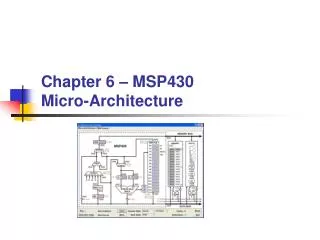
Architecture of the MSP430 Processor. Central Processing Unit. Program Counter (PC ) - C ontains the address of the next instruction to be executed . T he lsb of the PC is hardwired to 0

E N D
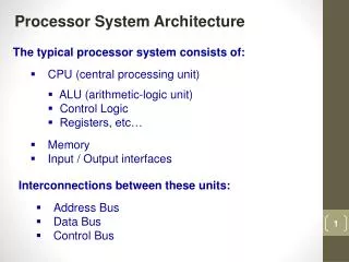
Central Processing Unit • Program Counter (PC) - Contains the address of the next instruction to be executed. The lsb of the PC is hardwired to 0 • Stack Pointer (SP) - The stack is heavily used for temporary variables,passing parameters to subroutines and returning the result, particularly for compiled languages. The stack pointer holds the address of the top of the stack. The lsb of the stack pointer is hardwired to 0 in the MSP430, which guarantees that it always points to valid words.
Status Register (SR) • This contains a set of flags (single bits). • Result of Arithmetic or Logic Operations: The C, Z, N, and V bits are affected by many of the operations performed by the ALU. • The carry bit C is to flag that the result of an arithmeticoperation is too large to fit in the space allocated. • The zero flag Z is set when the result of an operation is 0. • The negative flag N is made equal to the msb of the result, which indicates anegative number if the values are signed. • The signed overflow flag V is set when the result of a signed operation hasoverflowed, even though a carry may not be generated.
Status Register (SR) • Enable Interrupts - Setting the general interrupt enable or GIE bit enables maskable interrupts, provided thatthe individual sources of interrupts have themselves been enabled. • Control of Low-Power Modes - The CPUOFF, OSCOFF, SCG0 (system clk generator), and SCG1 bits control the mode of operation of the MCU.
Constant Generators • Both R2 and R3 are used to provide the 6 most commonly used constants. This savesstoring the values in the program and having to fetch them each time.
General-Purpose Registers • The remaining 12 registers R4–R15 have no dedicated purpose and may be used as generalworking registers. They may be used for either data or addresses because both are 16-bitvalues, which simplifies the operation significantly.
Addressing Modes • The ways in which operands can be specified. • Double operand (Format I): Arithmetic and logical operations with two operandssuch as add.w src, dst. accumulator-based architectures, where an accumulator or working register is used automatically as the destination and one operand. • Single operand (Format II): instructions for control or to manipulate a single operand. • Jumps: The jump to the destination rather than its absolute address, in other words theoffset that must be added to the program counter. • The “return from interrupt” instruction reti is unique in requiring no operands. Thiswould usually be described as inherent addressing but TI classifies it as Format II without data. ;
Register Mode • This uses one or two of the registers in the CPU. It is the most straightforward addressingmode and is available for both source and destination. • The registers are specified in the instruction word; no further data are needed. It is alsothe fastest mode and this instruction takes only 1 cycle. Any of the 16 registers can be usedfor either source or destination. • For byte instructions, • Operands are taken from the lower byte; the upper byte is not affected. • The result is written to the lower byte of the register and the upper byte is cleared. • The upper byte of a register in the CPU cannot be used as a source. If this is needed, the2 bytes in a word must first be swapped with swpb.
Indexed Mode • The address is formed by adding aconstant base address to the contents of a CPU register; the value in the register is notchanged. • Suppose that R5 contains the value 4 before this instruction:
Symbolic Mode (PC Relative) • In this case the program counter PC is used as the base address, so the constant is theoffset to the data from the PC. • TI calls this the symbolic mode although it is usuallydescribed as PC-relative addressing. • It is used by writing the symbol for a memorylocation without any prefix. • Instruction stores the value of LoopCtrin R6 using symbolic mode. • The assembler replaces this by the indexed form, • Where X = LoopCtr−PC is the offset that needs to be added to PC to get the address ofLoopCtr. • PC-relative addressing is essential to produce position-independent code.
Absolute Mode • The constant in this form of indexed addressing is the absolute address of the data. • Absolute addressing is shown by the prefix & and should be used for special function andperipheral registers, whose addresses are fixed in the memory map. • The assembler replaces this by the indexed form, • Where P1IN is the absolute address of the register.
SP-Relative Mode • TI does not claim this as a distinct mode of addressing. • Thestack pointer SP can be used as the register in indexed mode like any other. • This type of manipulation isimportant in subroutines and interrupts.
Indirect Register Mode • Shown by the symbol @ in front of a register,such as @R5. • The contents of R5 are used as the address of the operand. Inother words, R5 holds a pointer rather than a value (the contents of R5 would be theoperand itself if the @ were omitted). • Suppose that R5 contains the value 4, • Aword is loaded from address4 into R6. • Saves a word of program memory, which alsomakes it faster. • Thus the reverse of the preceding move must be done like this:
Indirect Autoincrement Register Mode • Shown by the symbol @ in front of aregister with a + sign after it, such as @R5+. It uses the value in R5 as a pointer andautomatically increments it afterward by 1 if a byte has been fetched or by 2 for a word. • Suppose that R5 contains the value 4, • A word is loaded from address 4 into R6 and the value in R5 is incremented to 6 because aword (2 bytes) was fetched. • The reverse of this move needs two instructions,
Indirect Autoincrement Register Mode • Autoincrement is usually called postincrement addressing because many processorshave a complementary predecrement addressing modebut theMSP430 does not. • An important feature of the addressing modes is that all operations on the first address arefully completed before the second address is evaluated. • The move itself might be done by a line, • Suppose that R5 initially contains the value 4. The contents of address 4 is readand R5 is double-incremented to 6 because a word is involved. The address forthe destination calculated as 0x0100 + 0x0006=0x0106. Thus a word is copied fromaddress 0x0004 to 0x0106; the offset is not just the value of 0x0100 used as the baseaddress for the destination. The compiler takes care of these details if you write inC, but you are on your own with assembly language.
Immediate Mode • This is a special case of autoincrement addressing that uses the program counter PC. • The instruction loads this word into R6 and increments PC to pointto the next word, which in this case is the next instruction. • Theword that followed the original instruction has been loaded into R6. • It is the equivalent of R6 = constant.
Constant Generator and Emulated Instructions • A complex instruction set computer (CISC) has special instructions for performing manycommon operations. • In contrast, a reduced instructionset computer (RISC) uses general instructions for these operations. • To improve efficiency, most RISCs therefore have one or more registers that are“hardwired” to commonly used values. • Dedicated constant generator R3/CG2. • The status registerR2/SR/CG1 acts as constant generator CG1when it is used as a source in the other three addressing modes. • These provide the base of 0 for absolute addressing, and the six immediatevalues 0, 1, 2, 4, 8, and 0xFFFF=−1 for signed values.
Constant Generator and Emulated Instructions • The chosen values are frequentlyused in comparison, arithmetic, and logic operations and for masks to pick out bits 0–3. • Direct (register) addressing of R3/CG2 returns the value 0, so mov.w R3,R5clears R5. Similarly, mov.w @R2,R5 uses indirect addressing on R2/SR/CG1, whichreturns the value 8 and this will be stored in R5. • These constants are combined with many of the 27 native instructions to provide a further24 emulated instructions.
Instruction Set • The instruction set is orthogonal, meaning that all addressing modes can be used with all instructions andregisters. • .w form for operations that can use either bytes or words. • Movement Instructions: There is only the one mov instruction to move data. • Stack Operations: These push data onto the stack and pop them off. • The SP is fixed to be even, so a word of stack space is always consumed, even if only abyte is added.
Arithmetic and Logic Instructions with Two Operands • Binary Arithmetic Instructions with Two Operands • The compare operation cmp is the same as subtraction sub except that only the bits in SRare affected; the result is not written back to the destination.
Arithmetic Instructions with One Operand • All these are emulated, which means that the operand is always a destination, • Decimal Arithmetic: These instructions are used when operands are binary-coded decimal (BCD) rather thanordinary binary values.
Logic Instructions with Two Operands • The and and bitwise test operations are identical except that bit is only atest and does not change its destination. • Logic Instructions with One Operand: There is only one of these, the invert inv instruction, aka ones complement,which changes all bits of 0 to 1 and those of 1 to 0.
Byte Manipulation • Operations on Bits in Status Register: There is a set of emulated instructions to set or clear the four lowest bits in the statusregister.
Shift and Rotate Instructions • Logical shift inserts zeroes for both right and left shifts. • Arithmetic shift inserts zeroes for left shifts but the most significant bit, whichcarries the sign, is replicated for right shifts. • Rotation does not introduce or lose any bits; bits that are moved out of one end ofthe register are passed around to the other.
Shift and Rotate Instructions • Usually the carry bit is included in rotations and it may gain the bit that is shifted out byarithmetic or logical shifts. • The MSP430 has arithmetic shifts and rotations, all of which use the carry bit. • Theright-shifts are native instructions but the left shifts are emulated, so the left-andright-shifts have different addressing modes available,
Flow of Control • Subroutines, Interrupts, and Branches: • Both br and call can use the full range of addressing modes for a source. • The most common use of call is for a subroutine that begins at a particularlabel. This label is translated by the assembler to the address of the first instruction in thesubroutine: direct addressing. This is the value that should be loaded into the PC to call thesubroutine and is therefore like immediate data. It must consequently be given the prefix #like any other immediate value. For example, call #DelayTenths. • Jump instructions useoffsets rather than full addresses and the compiler or assemblercalculates theseautomatically.
Jumps, Unconditional and Conditional • jmp fits in a single word, including the offset, but its range is limited to about±1KB from the current location. • br can go anywhere in the address space and use any addressing mode but isslower and requires an extra word of program storage. • The symbol $ stands for the current value ofthe program counter in the assembler so jmp $ is a concise way of getting an empty,infinite loop. • The conditional jumps are the “decision-making” instructions and test certain bits orcombinations in the status register. It is not possible to jump according to the value of anyother bits in SR or those in any other register. Typically a bit test instruction bit is used todetect the bit(s) of interest and set up the flags in SR before a jump.
Jumps, Unconditional and Conditional • Many branches have two names to reflect different usage. It is clearer to usejc if the carry bit is used explicitly—after a rotation, for instance—but jhs is moreappropriate after a comparison:
Breakdown of a Format I (double operand) instruction • Machine Code: • opcode (4 bits) is the operation code. The highest 12 values are used for Format Iinstructions, the remainder for jumps and Format II. • S-Reg and D-Reg (4 bits each) specify the CPU registers associated with thesource and destination; the registers either contain the operands themselves or theircontents are used to form the addresses. • As (2 bits) gives the mode of addressing for the source, which has four basic modes. • Ad (1 bit) similarly gives mode of addressing for the destination, which has onlytwo basic modes. • B/W (1 bit) chooses whether the operand is a byte (1) or a word (0).
Machine Code • The instruction can be broken into its fields of • opcode = 4, The opcode of 4 represents a move • S-reg = 5, The register isS-reg = 5, which is R5 as expected. • Ad = 0, The addressing mode for thedestination is Ad = 0, which is register. • B/W = 0,The bit B/W = 0 shows that the operand is a word. • As = 0, The addressing mode for the source is As =0. • D-reg = 6.The register is D-reg = 6 = R6.
Machine Code • The opcodeis 5.