Development of Plate Reformers with Electrically Heated Alumite Catalyst
This study compares different assignments of chambers in plate reformers and demonstrates the efficiency of electrically heated alumite catalysts. Transient temperature profiles and heat distribution are analyzed, highlighting the benefits of even temperature distribution in catalytic reactors.

Development of Plate Reformers with Electrically Heated Alumite Catalyst
E N D
Presentation Transcript
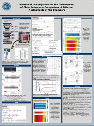
Numerical Investigations on the Developmentof Plate Reformers: Comparison of DifferentAssignments of the Chambers Introduction • Electrically Heated Alumite Catalyst is Combined with three layers i.e. two alumite layers (as the catalyst carrier ) and an alloy layer (high efficiency of the heat transfer, and can be heated by electricity) Figure 7. Transient profiles of the temperature distribution (a) in the reforming chamber and (b) in the combustion and preheating chamber with 3-min electrically heating. Fig.1 electrically heating profile of EHAC (endurance temperature : 1273 K) Result Model verification As Fig7(a) shows that the temperatures are greatly higher at the locations near the heater while the temperature shows rather even distributions at different radius locations when by electrical heat-up through EHAC (Fig 7 (b)). Since it is obvious that even temperature distribution can improve the reaction performance, the inside heat-up is preferred in the catalytic reactor. (a) (b) Fig. 2 the scheme of the reactor( for a clarity, the scheme is not drawn in real scale) (1)catalyst bed (2) pre-heating part (3)heater (4) thermal insulation material (5) thermocouples Figure 8. (a) Ordinary heat exchange system of the fuel processor26; (b) simplified heat exchange system of the fuel processor. AIChE Journal Reaactor Fig.4Temperature distribution in the reactor bed by different heat-up methods (a) heat-up by heater (b) electrical heat-up through the catalyst 2. Start-up performance of the reformer Reference [1] Zhang Q, Zhu X, KAMEYAMA H. Numerical investigations on the development of compact plate Reformers: comparison of different assignments of reformers’ chambers[J]. AIChE J., 2008, 54(10): 2707-2716. [2] Zhang Q, Guo Y, Zhou L. et al.Dynamics simulations of a novel heat-exchange methane reformer using a electrically heated alumite catalyst [J]. 化学工学論文集, 2008, 34(1): 113-118. [3] Zhou L, Guo Y, Zhang Q, et al.A plate-type anodic alumina supported nickel catalyst for methane steam reforming [J]. J. Chem. Eng. Japan, 2008, 41(2): 90-99. [4] Zhang Q, Takahashi H., Nagaya M, et al. Simulation and experimental analysis on the development of the co-axial cylinder methane steam reformer using the electrically heated alumite catalyst [J]. Int. J. Hydrogen Energy, 2007, 32(16):3870-3879. [5] Zhang Q, Guo Y, Zhou L, et al. Development of the methane steam reformer using an electrically heated alumite catalyst: Start-up performance investigated by the numerical and experimental analysis [J]. J. Chem. Eng. Japan, 2007, 40(6):487-496. [6] Zhang Q, Sakurai M, Kameyama H. Performance simulations of a compact plate methane steam reformer using electrically heated alumite catalyst [J]. J. Chem. Eng. Japan, 2007, 40(4):319-328 . [7] Guo Y, Tran T, Q. Zhang et al. Steam methane reforming using an anodic alumina supported nickel catalyst (Ni/Al2O3/Alloy): analysis of catalyst deactivation [J]. J. Chem. Eng. Japan, 2007, 40(13): 1121-1128. Figure 5. Effects of the fuel ratio on the reforming performance and heat point temperature for thePHER Figure 3. (a) Cross section photo of the EHAC; (b) Heat exchange reformer (HER); (c) Heat exchange reformer coupled with preheating chamber (PHER). (For clarity, the schemes are not drawn in a real scale). Figuter Model Figure 6. (a) Velocity field surface and stream line profiles in the PHER for (a-1) reforming chamber and (a-2) combustion 1 preheating chambers; (b) temperature distribution and contour profiles in the (b-1) reforming chamber and (b-2) combustion 1 preheating chambers. Model Equations