Advanced CNC Machine Project with Multiple Tool Heads
This project aims to create a versatile CNC machine for manufacturers and hobbyists at competitive costs. It features multiple tool heads for various applications and efficient communication via serial port, Ethernet, or USB. The machine operates at high speeds with long-term durability.

Advanced CNC Machine Project with Multiple Tool Heads
E N D
Presentation Transcript
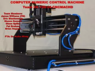
COMPUTER NUMERIC CONTROL MACHINE Team 24: F09-24-CNCMACHD Team Members: James Williams (PM) Eric Blankenship Shawn Gossett Glenn Spiller Pat Brokaw Brian Hagene FTA: Dr. Haibo Wang
Outline Executive SummaryJames CNC Diagram James Machine Subsystems • Mechanical Pat & Brian • Motor Drive Eric • Main Controller Glenn • Pendent Shawn Cost Breakdown James Implementation ScheduleBrian Summary Brian Acknowledgements
Executive Summary Project Objective • A CNC Machine that can be used not only by manufacturers but also by small scale hobbyists at costs much less than competitors. • Three forms of communication either through serial port, Ethernet, or USB jump drive • Controllable through a specially designed hand pendant • Multiple tool heads for different applications including milling, paste dispensing, and air brushing • Able to move at high speeds with longer working life compared to other relative machines Why Needed • Other machines perform only one specific task • Loading different programs by current methods result in longer machine down times and loss in revenue.
Mechanical Subsystem Base X Axis Y Axis Z Axis
Mechanical Subsystem Base • Table Specifications: • Table Work Area: 1160 in2 • Maximum Part Weight: +18 lbs • Table Supported by Rail: 0.375 in x 1 in • Y-Axis Rail Design: • Length: 38 in • Weight Supported: 40 lbs • Length and Weight was significant • Guide system selected: Supported rail Y Axis
Mechanical Subsystem X Axis • Designed Considerations: • 5.5 lb cutting force • 10 lb tool head • 100 lb.in moment due to weight • 75 lb.in moment due to cutting force • Design Specifications: • X-Rod Diameter: 1.18 in (30mm) • Rod Spacing: 4 in • Supports 37.8 lbs/rod • Maximum deflection: 0.001 in • System Loads: • 26.70 lbs, 15.63 lbs, 22.53 lbs • Alternative Design: • 4 Rods with 15.63 lbs/rod • Rod Diameter : 1 in • Cost increases
Mechanical Subsystem Z Axis • Z-Axis Design Considerations: • Minimize moment about x-axis ballscrew • Guide system selected: Versa rails • Moves tool head closer to center of x-axis • Alternative Design: • 2 Guide Rods • Increases moment
Mechanical Subsystem • Ballscrew Drive Specifications: • Lead: 0.2 in/rev • Diameter: 5/8 in • Supports: Ball bearing & Thrust bearing block assembly • Thrust Forces: • Acceleration 28.9 lbs • -Static friction and acceleration force • Constant Velocity 18.8 lbs • -Only kinetic friction
Mechanical Subsystem • Tool Head Options: • Spindle • Paste dispenser
Motor Drive Assembly • Purpose: Power Motors to drive ballscrews, providing motion in 3 dimensions
Motor Design Requirements • Provide a minimum 20oz.in of torque at a speed of 4 in/sec. Required to move each axis. • Be cable of providing a minimum torque safety factor of 100%.
Motor Specifications Motor sizes: • 276 oz.in (X-axis & Y-axis) • 166 oz.in (Z-axis) Motor Requirements: • 2.8 amps/phase • Voltage of approx. 48 volts for a torque of 80oz.in at 4in/sec.
Motor Driver Considerations Requirements: • step and direction inputs to move motors • Cable of driving motors at a minimum of 2.8 amps. • Surface mount chips to save space. Selected: • Allegro A3986 [micro-stepping sequencer]
Motor Driver Considerations Other design requirements • Low power dissipation: Mosfet H-Bridge with very low on resistance. (.050 ohm) • Current sense resistor: very low resistance (.043 ohms) • Traces :2 oz vs. 1 oz copper. • To Provide low trace inductance to reduce high voltage spikes from destroying chips. Provide low power dissipation for motor traces. • Power Transformer selection: provide power to motors that would fit into small cabinet with minimum stray magnet fields. • System monitoring and fault identification: fuses and LEDs added to aid trouble shooting and protect circuit
Motor Drive Subsystem Motor Drive Subsystem • Features • Pulse width modulation, MOSFET H-Bridge • Motor size from 2 to 4.7 amps • Optical Isolation for all inputs • Full, Half, 1/4, 1/16 step resolution • Over Current Protection • Over temperature and under voltage protection • Fuse Blown Indicators (3 LED’s) • 5 V supply Good LED • Outputs to Controller • Drive Board Ready Signal • Drive Board Fault Signal • Motor Power Supply Ready Signal
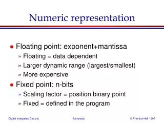
Main Controller Subsystem • Ethernet Microprocessor • ENC624J600 (Microchip Technology) • Communication Controller • PIC24FJ256GB110 (Microchip Technology) • Motion Controller • PIC24HJ256GP610 (Microchip Technology) PIC24HJ256GP610 PIC24FJ256GB110 ENC624J600
PIC24FJ256GB110 • 24 bit 100 pin micro-processor is used to control the communications for the CNC. • Any data that comes into the the Controller board goes thorough the Communication micro controller. • Specific requirements: • 1 – SPI • 2 – UART • 8 – Data Pins • 16– Address Pins • Connections to the Com controller: • RS232 • Serial • USB to Go • Ethernet • VGA(Output)
ENC624J600 • 64 pin micro-controller specifically for Ethernet implementation. • No programming was needed for this chip. It comes pre-configured to take Ethernet data. This micro chip connects directly to the Com Controller • Specific Requirements: • 1 – SPI • External Connections: • RJ45 Connector
PIC24HJ256GP610 24 bit micro-controller used to take the data from the communication micro chip and distribute Data to the motor driver board. Specific Requirements: 2 – SPI (to communication) 1 – UART (to Pendent) 8 – Data Input Pins 4 – External Interrupts
Interconnects from the main controller to the motor driver board.
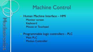
Pendent Subsystem Case Screen
Pendent Subsystem • Requirements • LCD Screen • Four buttons for accessing different function screens, accepting a command, canceling a command, and switching the axis between y and z on up and down directional buttons • Four buttons to change direction on x, y, or z axes • Feed pot dial to increase or decrease feed/speed rates
Pendent Subsystem • Casing • Upper section will have a width of 5 inches and a length of around 2.5 inches • Placement for LCD Screen, Function button, Accept Button, Cancel Button, Axis Switch Button, and Feed Pot Override • Lower section will have a width 3 inches and a length of 3.5 inches • Placement for X, Y, and Z directional buttons
Pendent Subsystem • System Diagram • LCD Screen • PIC 24 Microcontroller • DB9 and MAX32 • Receive and transmit information from main controller system to pendant system • Voltage Regulator • Input of 5 volts to make controlled output of 3.3 volts • Feed pot/Potentiometer • Control of feed/speed rate • Clock chip • Steady, constant flow of information • Switch buttons
Pendent Subsystem • PCB Layout • Top Layer • LCD Screen • Top four buttons are function, accept, cancel, and axis switch • Bottom four buttons are four axis direction movement • Left and right control x axis • Top and bottom control y or z axes • Bottom Layer • Remaining Components • Tightly packed to prevent losses • Connector at bottom to attach to main controller system
Pendent Subsystem • Screens • Main Screen • Upper left box contains current x, y, z, and acceleration axes • Lower left box contains circles for limit switches which will either be red/green to show on/off • Upper right box contains current adjustment of feed pot ranging from +-50 % of the rated value • Lower right box displays the current state of the machine which can be jog, idle, or run • Other Screens • All Sub Screens • Offsets Screens- Home, Park, Work Offset 1, Work Offset 2 • Soft Limits Screens- Upper and Lower • Parameters Screens- Machine Parameters, TCP/IP Configuration, Communications Port • Flash Drive Screen
Costs • The Mechanical Total comprises of: • Frame • Bolts • Ballscrews • Rods • Shafts • The Electrical Total comprises of: • Circuit Chips • Driver Boards • Controller Boards • Pendent
Implementation Schedule Each component requires different time frames to finish each subassembly. The construction is simple once all subassemblies are finished, and the machine can be fully assembled in a 4 hour period with a three man team. The machine is ready for operation after testing is complete.
Summary Looked at the Machine Layout Went through the Subsystems and Considerations – Mechanical – Motor Driver – Main Controller – Pendent Went over detailed Cost Breakdown Looked at Implementation Schedule
Acknowledgements • Dr. Haibo Wang- Faculty Technical Advisor • Mr. Mark Hopkins- Technician/ Field Engineer for Allegro Micro-devices • Mr. Howard Everton- President of Norva Plastics • Barb Saathoff- Representative from Dytronix • Tim Attig- Mechanical Shop Machinist