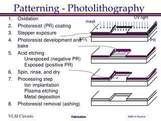
Photolithography Machine Control System
Photolithography Machine Control System. Ben Conrad and Mark Edwards Projects in Computer Engineering II December 9, 2003. System Overview – Solitec 8360. Used in the photolithography process to evenly apply chemicals to wafers 25 200mm wafer capacity

Photolithography Machine Control System
E N D
Presentation Transcript
Photolithography Machine Control System Ben Conrad and Mark Edwards Projects in Computer Engineering II December 9, 2003
System Overview – Solitec 8360 • Used in the photolithography process to evenly apply chemicals to wafers • 25 200mm wafer capacity • Main components: Wafer input cartridge, wafer output cartridge, spin chuck, bake chuck, system tray Spin Chuck Vacuum Tube Bake Chuck Vacuum Tube Wafer Output Cartridge (25 wafers) Wafer Input Cartridge (25 wafers)
System Overview – Solitec 8360 • Wafer Load • Processing on Spin Chuck • Bake on Bake Chuck • Multipass Mode Check • Wafer Egress
System Controller • Provides an interface between the operator and the control unit. • Formats data for display to the user • Interprets and forwards user requests and input to the control unit
System Controller Cont’ • Control the system’s mode of operation • Three operating modes • Service: manual system operation • Program: writing and editing of recipes • Run: recipe execution/system calibration
Recipe Commands • Seven Executable Commands • PREWET: Dispense de-ionized(DI) water • Dispense DEV#1: Dispense developer solution • RINSE: Dispenses DI water to clean wafer • N2: Dispenses Stream of Nitrogen (N2) • SPIN: Spin Dry the wafer • WAIT: Static delay option. • Parameters • Time: .1 – 999.9 sec. (.1 second resolution) • Speed: 0-7,999 RPM • Ramp: 0 – 40 KRPM/s
Motivation • Old controller was corroded; less elements in our design -> more reliable • Cost savings to customer, Dr. Raisanen, associate director of RIT’s fab • Our design ~$350, vs. $3k-$15k
Feasibility • Motor Control Board will be reused – no digital controller need be implemented • Other than 3 analog, all I/0 are TTL digital logic, no conditioning needed • Sensors have been tested and functionality for most is verified • Timing Budget: Asynchronous System
System Design- High Level • The STD Bus will be replaced with a HC12-s microcontroller • A HC11 will be connected to the HC12 via SPI protocol to handle UI • Custom Circuits are created to multiplex numerous I/0 lines to the HC12’s limited pins
HC12 A/D Servo Board 2 8-bit DACs S Keypad and LCD HC 11 P 1 16-bit serial in, parallel out shifter 50 Pin Out Cable B 2 16-bit parallel in, serial out shift registers for input = 32 input bits 50 Pin Input Cable A 3 16-bit serial in, parallel out shift registers for output = 48 output bits System Design – High Level
System Controller Hardware • Input • 4x4 Matrix keypad • Interrupt driven • SPI bus • Three wire interface to digital controller • Used to communicate status and display information
System Controller H/W Cont’ • Output • 40x4 Character LCD display • SPI bus • Forwards user input the control unit. • Status Lights • Run mode • Program mode • End of Processing • Interlock
System Controller H/W Cont’ • Processing unit • Motorola 68HC11 • 512 bytes RAM, 512 bytes EEPROM • Synchronous peripheral interface (SPI) • Real time interrupt circuit • Data aggregation • Distribute workload
System Design – System I/O Shows the detailed HC-12 Control Unit I/O connections
System Software Design Run mode flowchart
System Software Design • Task control block(TCB) • Tracks the processing of a single wafer
Already Completed • Parts ordered and received • Hardware schematics • Software flowcharts • Task control design • Sensor/System tests
Expected Difficulties • Unreliability of mechanical system • No ability to completely test system • Servo control board - analog signals • Overall system complexity