Datapath and Control
CDA 3101 Discussion Section10. Datapath and Control. Questions.

Datapath and Control
E N D
Presentation Transcript
CDA 3101 Discussion Section10 Datapath and Control
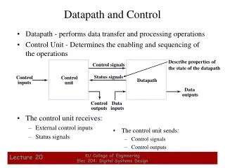
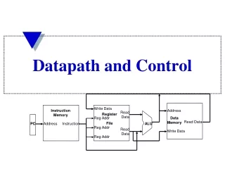
Questions 5.3 Describe the effect that a single stuck-at-1 fault (the signal is always 1) would have for the signals shown below, in the single-cycle datapath in Figure 5.17 on page 307. Which instructions, if any will not work correctly? Explain why. • RegWrite • ALUOp0 • ALUOp1 • Branch • MemRead • MemWrite
ALU Control Figure 5.12 How the ALU control bits are set depends on the ALUOp control bits and the different function codes for the R-type instruction. Figure 5.18 The setting of the control lines is completely determined by the opcode fields of the instruction.
Question 5.3 0 • RegWrite=1 • sw and beq should not write results to the register file. sw(beq) will overwrite a random register with either the store address (branch target) or random data from the memory data read port. • ALUOp1=1 • The R-Type instructions will work fine. Lw and sw will not work if the bits 0-5 of the instruction representation is anything other than the function code for add. beq will not work unless the bits 0-5 of the instruction representation is the function code for subtract. • ALUOp0=1 • beq will work fine. lw and sw will not work fine because a subtraction will be done instead of addition. Some R-Type instructions will work, others will not.
Question 5.3 • Branch=1 • Instructions other than branches (beq) will not work correctly if the ALU Zero signal is raised. An R-format instruction that produces zero output will branch to a random address determined by its least significant 16 bits. • MemRead=1 • All instructions but sw will work correctly. (Data memory is always read, but memory data is never written to the register file except in the case of lw.) sw will not work because both MemRead and MemWrite should not be set to 1 at the same time. • MemWrite=1 • Only sw will work correctly. The rest of instructions will store their results in the data memory, while they should not.
Questions 5.8 Add the instruction jr to the single-cycle datapath described in this chapter. Add any necessary datapaths and control signals to the single-cycle datapath of Figure 5.17 on page 307 and show the necessary additions to Figure 5.18 on page 308. Jump Register – jr rs • PC=R[rs] • R-type, Op/Fun code: 0/0x08
Question 5.8 X 0 M U X 1 JumpReg Instruction[5-0]