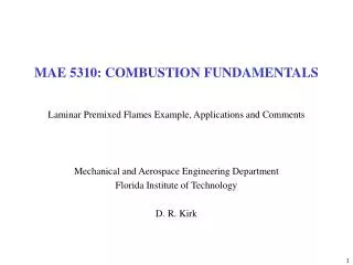
MAE 5310: COMBUSTION FUNDAMENTALS
260 likes | 645 Vues
MAE 5310: COMBUSTION FUNDAMENTALS. Laminar Premixed Flames Example, Applications and Comments Mechanical and Aerospace Engineering Department Florida Institute of Technology D. R. Kirk. LAMINAR PRE-MIXED FLAME EXAMPLE.

MAE 5310: COMBUSTION FUNDAMENTALS
E N D
Presentation Transcript
MAE 5310: COMBUSTION FUNDAMENTALS Laminar Premixed Flames Example, Applications and Comments Mechanical and Aerospace Engineering Department Florida Institute of Technology D. R. Kirk
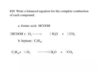
LAMINAR PRE-MIXED FLAME EXAMPLE • Estimate the laminar flame speed, SL, of a stoichiometric propane (C3H8)-air mixture using the simplified theory of Spalding developed in class • Make use of a global, one-step reaction mechanism to estimate the mean reaction rate Laminar flame structure. Temperature and heat-release rate profiles based on experiments of Friedman and Burke Reference: Turns An Introduction to Combustion
PRINCIPAL CHARACTERISTICS OF LAMINAR PREMIXED FLAMES • Definition of flame speed, SL • Temperature profile through flame • Product density is less than the reactant density so that by continuity the velocity of the burned gases is greater than the velocity of the unburned gases • For a typical hydrocarbon-air flame at atmospheric pressure, the density ratio is about 7 • Convenient to divide the flame into two zones • Preheat zone: little heat is released • Reaction zone: most of the chemical energy is released 2.a Thin region of fast chemistry • Destruction of fuel molecules and creation of intermediate species • Dominated by bimolecular reactions • At atmospheric pressure, fast zone is usually less than 1 mm • Temperature and species concentration gradients are very large • The large gradients provide the driving forces for the flame to be self-sustaining, i.e. diffusion of heat and radical species from the reaction zone to the preheat zone 2.b Wider region of slow chemistry • Chemistry is dominated by three-body radical recombination reactions, such as the final burn-out of CO via CO + OH → CO2 + H • At atmospheric pressure, this zone may extend several mm
LAMINAR PREMIXED FLAMES: SIMPLIFIED ANALYSIS • Analysis couples principles of heat transfer, mass transfer, chemical kinetics, and thermodynamics to understand the factors governing: • Flame speed, SL • Flame thickness, d (ANSWER, d=2a/SL) • Simplified approach using conservation relations • Assumptions: • 1-D, constant area, steady flow • Neglect: kinetic and potential energy, viscous shear work, thermal radiation • Constant pressure (neglect small pressure difference across flame) • Diffusion of heat governed by Fourier’s law • Diffusion of mass governed by Fick’s law (binary diffusion) • Lewis number (Le≡a/D) unity • Individual specific heats are equal and constant • Fuel and oxidizer form products in a single-step exothermic reaction • Oxidizer is present in stoichiometric or excess proportions; thus, the fuel is completely consumed at the flame.
VON KARMAN INTEGRAL ANALYSIS OF F.P.B.L. Compare with development of Equation 8.7b
USEFUL DATA AND EQUATIONS Pay attention to units conversion (see WSR example for C2H6) Theoretical expression for laminar flame speed, SL Premixed laminar flame thickness, d
DETAILED ANALYSIS USING CHEMKIN: CH4-AIR PREMIXED LAMINAR FLAME • Figure (a) shows principal C-containing species CH4, CO, and CO2. • Note disappearance of fuel and appearance of intermediate CO, and burn-out of CO to form CO2 • CO concentration has peak value at approx same location where CH4 concentration goes to zero • CO2 concentration at first lags CO concentration but then continues to rise as CO is oxidized • Figure (b) shows C-containing intermediate species CH3, CH2O, and HCO, which are produced and destroyed in a narrow interval from approximately 0.4 mm – 1.1 mm. • Figure (d) shows same phenomena for the CH radical • Figure (c) shows that H-intermediates, HO2 and H2O2 have somewhat broader profiles than C-intermediates. Peak concentrations appear slightly earlier in flame. • H2O mole fractions reaches its 80% of equilibrium value (at about 0.9 mm) sooner than CO2 (at about 2mm) • All fuel has been destroyed in approx. 1 mm and most of total temperature rise (~ 75%) occurs in same interval • Approach to equilibrium is relatively slow beyond this point (no equilibrium even at 3 mm) • Slow approach toward equilibrium is a consequence of dominance of 3-body recombinations • Figure (d) shows NO production • Rapid rise in NO mole fraction in same region where CH radical is present in flame • This is followed by a continual (almost linear) increase in NO mole fraction. In this later region NO formation is dominated by Zeldovich kinetics. • Curve ultimately bends over as reverse reactions become more important and equilibrium is approached asymptotically
DETAILED ANALYSIS USING CHEMKIN: CH4-AIR PREMIXED LAMINAR FLAME • Plot shows molar production / destruction rates for various species and provides more insight into CH4→ CO → CO2 sequence • Peak fuel destruction rate nominally corresponds with peak CO production rate • CO2 production rate initially lags that of CO • Even before location where there is no longer any CH4 to produce additional CO, the net CO production rate becomes negative (CO is being destroyed) • Maximum rate of CO destruction occurs just downstream of peak CO2 production rate • Bulk of chemical activity is contained in an interval extending from about 0.5 mm to 1.5 mm
DETAILED ANALYSIS USING CHEMKIN: CH4-AIR PREMIXED LAMINAR FLAME • Plot shows NO production rate through flame • Figure shows that early appearance of NO within flame (0.5 mm – 0.8 mm see Figure (d)) is result of passive diffusion since production rate is essentially zero in that region. • First chemical activity associated with NO is a destructive process in region approximately 0.8 mm – 0.9 mm. • NO production reaches a maximum at an axial location between CH and O-atom concentrations. It is likely that both Fenimore and Zeldovich pathways are important (see p.168-171 or Turns. • Beyond O-atom peak at a distance of 1.2 mm (Figure (d)), NO production rate falls. Since temperature continues to rise in this region, decline in net NO production rate must be a consequence of decaying O-atom concentration and building strength of reverse reactions.
FACTORS INFLUENCING SL AND d • Scaling relation developed on p. 274-275 • Laminar flame speed has a strong temperature dependence • Global reaction orders for HC ~ 2 • EA ~ 1.67x10⁸ J/kmol • Example: CASE A vs. CASE B • SL increases by a factor of 3.64 when the unburned gas temperature is increased from 300 K to 600 K • Increasing unburned gas temperature will also increase the burned gas temperature by the same amount (neglect dissociation and variable specific heats) • Example: CASE A vs. CASE C • Case C forces a lower Tb • Captures the effect of heat transfer of changing equivalence ratio, either rich or lean, from the maximum-temperature condition.
LAMINAR FLAME SPEED (T&P) SCALING: USEFUL DATA Experimental measurements generally show a negative pressure dependence Plot is for CH4 - Air SL (cm/s) = 43P-0.5 (atm) Plot is for CH4 – Air f=1.0 P=1 atm Primary effect of f is through flame temperature Max slightly rich of f=1.0
LAMINAR FLAME SPEED FOR VARIOUS FUELS • Comment on H2 • Thermal diffusivity of H2 is many times greater than HC fuels • Mass diffusivity of H2 is much greater than HC fuels • Reaction kinetics for H2 are very rapid (no slow CO → CO2 step) Laminar flame speeds for pure Fuels burning in air at f = 1.0 P = 1 atm, Tu = 300K
FLAME SPEED CORRELATIONS FOR SELECTED FUELS • One of most useful correlations for laminar flame speed, SL, given by Metghalchi and Keck • Determined experimentally over a range of temperatures and pressures typical of those found in reciprocating IC engines and gas-turbine combustors • EXAMPLE: Employ correlation of Metghalchi and Keck to compare laminar flame speed gasoline (RMFD-303)-air mixtures with f = 0.8 for 3 cases: • At reference conditions of T = 298 K and P = 1 atm • At conditions typical of a spark ignition engine operating at T = 685 K and P = 18.38 atm • At same conditions as (2) but with 15 percent (by mass) exhaust gas recirculation
TRANSIENT BEHAVIOR • 3 important aspects to consider • Quenching distance • Critical diameter of a circular tube where a flame extinguishes, rather than propagates • Flammability limits • Lower limit: leanest mixture (f<1) that will allow steady flame propagation • Upper limit: richest mixture (f>1) that will allow steady flame propagation • Minimum ignition energy • In each of these, heat loss is the controlling phenomena • Ignition and Quenching Criteria (also called Williams’ criteria): • Ignition will only occur if enough energy is added to the gas to heat a slab about as thick as a steadily propagating laminar flame to the adiabatic flame temperature • The rate of liberation of heat by chemical reactions inside the slab must approximately balance the rate of heat loss from the slab by thermal conduction • Keep in mind that (1) and (2) are just rules-of-thumb
EXAMPLE: FLAME ARRESTERS Flame arresters on boat motor Davey Miner’s Safety Lamp The screen's ability to dissipate heat and prevent combustion while allowing flammable mixtures of gases to pass through has been used in practical applications. Sir Humphrey Davy used this principle in his invention of the miner's safety lamp in 1815. Flammable gases from the mine could pass through the screen and burn in the enclosed flame with a 'colored haze' while the screen prevented the open flame from causing a mine explosion Flame arresters are used to prevent propagation of flame fronts in process piping
QUENCHING DISTANCE, FLAMMABILITY LIMITS, AND MINIMUM IGNITION ENERGY CH4-Air at 1 atm Laminar flame speeds for pure Fuels burning in air at f = 1.0 P = 1 atm, Tu = 300K
FLAMMABILITY LIMITS • Experiments show that a flame will propagate only within a range of mixture compositions (sometimes called mixture strengths in this context) between lower and upper limits of flammability • Lower limit is leanest mixture (f < 1) that will allow steady flame propagation • Upper limit is richest mixture (f > 1) that will allow steady flame propagation • Flammability limits are frequently quoted as percent fuel by volume in mixture, or as a percentage of the stoichiometric fuel requirement • Experimental determination: Tube Method • Determine whether or not a flame initiated at the bottom of a vertical tube (approximately 50 mm diameter and 1.2 m long) propagates the length of tube • A mixture that sustains the flame is said to be flammable and by adjusting the mixture strength, flammability limit can be ascertained • In addition to mixture properties, experimental flammability limits are related to heat losses from the system, and hence, are generally apparatus dependent • Example: A full propane cylinder from a stove leaks contents of 1.02 lb (0.464 kg) into a 12’ x 14’ x 8’ (3.66 m x 4.27 m x 2.44 m) room at 20 ºC and 1 atm. After a long time, the fuel gas and the room air are well mixed. Is mixture in room flammable?
IGNITION • GOAL: Estimate minimum ignition energy, Eign, as a function of T & P • CRITERIA: Volume of gaseous reactants heated during ignition must be large enough so that when ignition source is removed, heat loss to the surroundings will not exceed the chemical energy release rate.
FLAME STABILIZATION COMMENTS • Both Flashback and Liftoff are related to matching local laminar flame speed to local flow velocity • Flashback occurs when the flame enters and propagates through the burner tube without quenching • Can be dangerous and can lead to explosions • Can be useful as a ‘flash tube’ from pilot flame to a burner • Occurs when local flame speed exceeds local flow velocity (when fuel flow is being decreased or turned off – transient event) • Controlling parameters: fuel type, equivalence ratio, flow velocity, and burner geometry (same parameters that control quenching) • Liftoff is the condition where the flame is not attached to the burner tube but is stabilized at some distance from the port • Can lead to escape or loss of unburned gases • Can lead to incomplete combustion • Ignition is often difficult above lifting limit • Tough to accurately control position of flame • Poor heat transfer • Flame can be noisy
FLAME STABILIZATION COMMENTS • Liftoff depends on local flame and flow properties near the edges of the burner port • Liftoff and blowoff can be explained by the countervailing effects of decreased heat and radical loss to burner and increased dilution with ambient air, both occur when flow velocity is increased • Consider a flame that is stabilized close to burner rim • Local flow velocity at stabilization location is small because of boundary layer (Vwall=0) • Because flame is close to cold wall, both heat and reactive species diffuse to wall, which leads to small SL • With SL and flow velocities small and equal, flame edge lies close to burner tube • When flow velocity is increased, flame anchor point moves downstream • SL increases since heat/radical losses are less because flame is now not as close to cold wall • Increase in SL results in only a small downstream adjustment • Flame remains attached • Now increase flow velocity further • New effect is important: dilution of mixture with ambient air as a result of diffusion • Dilution tends to offset effects of heat loss and flame lifts • With further increases in flow velocity, a point is reached at which there is no location across the flow at which the SL matches the flow velocity, and the flame blows off the tube
FLAME STABILIZATION http://liftoff.msfc.nasa.gov/shuttle/usmp4/science/elf_obj.html