Understanding Subroutines and Interrupts in LC-3 Assembly Language
This guide covers essential concepts of subroutines and interrupts in LC-3 assembly programming. It explains the mechanics of the JSR and JSRR instructions for calling subroutines, how return operations are performed with the RET instruction, and the differences between subroutines and traps. Additionally, it introduces stack operations (push and pop) essential for subroutines, including handling underflow and overflow errors. Finally, it provides an overview of enabling and processing interrupts, detailing the role of the Processor Status Register (PSR) in ensuring smooth execution.

Understanding Subroutines and Interrupts in LC-3 Assembly Language
E N D
Presentation Transcript
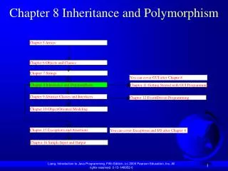
Chapter 9 & 10 Subroutines and Interrupts
Subroutines JSR Instruction: JSR offset (11 bit) 0100 1 xxxxxxxxxxx [PC ] R7, JMP Offset Jump to Subroutine at offset from PC JSRR Instruction: JSRR Rb 0100 0 00 xxx 000000 [PC ] R7, JMP [Reg] Jump to Subroutine at address in Rb Return: RET 1100 000 111 000000 C1C0 [R7] PC (JMP [R7]) Return to Instruction after Jump to Subroutine (or TRAP)
Subroutines • Execute JSR or JSRR - Call Subroutine or Method 2) Location of Subroutine is specified in the Instruction 3) [PC] stored in R7 4) Address from JSR or JSRR is loaded into PC 5) Subroutine is executed R0 likely contains passed parameter (or address) R5 may be used to return error message R0 likely contains return parameter (or address) 6) Subroutine program ends with an RET ( [R7] loaded into PC) How does this mechanism support recursion? It doesn’t! Implement a stack to accommodate recursion.
Subroutines vs Traps How are Subroutines different from Traps ? • Traps are called using the TRAP instruction (Indirect call through the Trap Vector Table) Subroutines are called using JSR or JSRR instructions (JSR Direct call, JSRR Indirect call) • Both end with a RET ( load the return address) A Trap is an Subroutine call (Indirect) through a Vector Table (the Trap Vector Table [x0000-x00FF]).
Stack R6 is the Stack Ptr Push: Push ADD R6, R6, #-1 ; Decrement Stack Ptr STR R0, R6, #0 ; “Push” Data onto Stack Pop: Pop LDR R0, R6, #0 ; “Pop” Data off of Stack ADD R6, R6, #1 ; Increment Stack Ptr Which way does the Stack grow? Where does Stack Ptr (R6) point?
Underflow Pop LD R1, Empty ; Compare Stack Ptr with x4000 ADD R2, R6, R1 BRz Underflow ; Underflow Error if nothing to Pop (Stack Empty) LDR R0, R6, #0 ; Pop Data ADD R6, R6, #1 ; Inc Stack Ptr AND R5, R5, #0 ; “Report” no error 0 R5 RET Underflow AND R5, R5, #0 ; “Report Error” 1 R5 ADD R5, R5, #1 RET Empty .FILL xC000 ; Empty -x4000 (Beginning of Stack is 3FFF)
Overflow Push LD R1, Full ; Compare Stack Ptr with Top of Stack (255 entries) ADD R2, R6, R1 BRz Overflow ; Overflow Error if no room to Push (Stack full) ADD R6, R6, #-1 ; Dec Stack Ptr STR R0, R6, #0 ; Push Data AND R5, R5, #0 ; “Report” no error 0 R5 RET Overflow AND R5, R5, #0 ; “Report Error” 1 R5 ADD R5, R5, #1 RET max .FILL xC100 ; Full x3F00 (Top of Stack is xC0FF)
Subroutine for Push & Pop ; Subroutines for carrying out the PUSH and POP functions. ; R6 is the stack pointer. R0 contains Data. R5 contains Error Report ; Stack: x3FFF (BASE) through x3FFB (MAX).; POP ST R2,Save2 ; are needed by POP. ST R1,Save1 LD R1,BASE ; BASE contains -x3FFF. ADD R1,R1,#-1 ; R1 contains -x4000. ADD R2,R6,R1 ; Compare stack pointer to x4000 BRz fail_exit ; Branch if stack is empty. LDR R0,R6,#0 ; The actual "pop." ADD R6,R6,#1 ; Adjust stack pointer BRnzp success_exit PUSH ST R2,Save2 ; Save registers that ST R1,Save1 ; are needed by PUSH. LD R1,MAX ; MAX contains -x3FFB ADD R2,R6,R1 ; Compare stack pointer to -x3FFB BRz fail_exit ; Branch if stack is full. ADD R6,R6,#-1 ; Adjust stack pointer STR R0,R6,#0 ; The actual "push" success_exit LD R1,Save1 ; Restore original LD R2,Save2 ; register values. AND R5,R5,#0 ; R5 <-- success. RET fail_exit LD R1,Save1 ; Restore original LD R2,Save2 ; register values. AND R5,R5,#0 ADD R5,R5,#1 ; R5 <-- failure. RET BASE .FILL xC001 ; BASE contains -x3FFF. MAX .FILL xC005 Save1 .FILL x0000 Save2 .FILL x0000 .END
State of Program - Program Status Register PSR (PSW): PSR[15] – Privilege Bit PSR[10:8] – Priority Bits PSR[2:0] – Condition codes - N, Z, P
Interrupts • Programmer Action: Enable Interrupts by setting “intr enable” bit in Device Status Reg • Enabling Mechanism for device: When device wants service, and its enable bit is set (The I/O device has the right to request service), and its priority is higher than the priority of the presently running program, and execution of an instruction is complete, then The processor initiates the interrupt • Process to service the interrupt: The Processor saves the “state” of the program (has to be able to return) The Processor goes into Privileged Mode (PSR bit 15 cleared) Priority level is set (established by the interrupting device) The (USP), (R6) USP.saved register (UserStackPointer.saved) The (SSP.saved) R6 (SupervisorStackPointer) The (PC) and the (PSR) are PUSHED onto the Supervisor Stack The contents of the other registers are not saved. Why? The CC’s are cleared • The Processor Loads the PC from the Interrupt vector (vectors in 0100:01FF) • Interrupt Service Routine is executed Ends with an RTI • The stored user PSR (POP into PSR), PC (POP into PC), (R6)SSP.saved, (USP.savedR6), and the next instruction fetched
Interrupt Example Memory Maps SSP & PC