Review: Major Components of a Computer
260 likes | 468 Vues
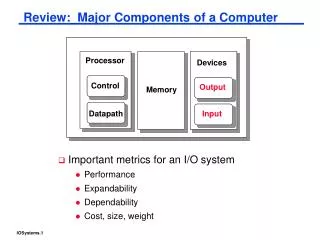
Review: Major Components of a Computer. Important metrics for an I/O system Performance Expandability Dependability Cost, size, weight. Processor. Devices. Control. Output. Memory. Datapath. Input. 8 orders of magnitude range. Input and Output Devices.

Review: Major Components of a Computer
E N D
Presentation Transcript
Review: Major Components of a Computer • Important metrics for an I/O system • Performance • Expandability • Dependability • Cost, size, weight Processor Devices Control Output Memory Datapath Input
8 orders of magnitude range Input and Output Devices • I/O devices are incredibly diverse with respect to • Behavior – input, output or storage • Partner – human or machine • Data rate – the peak rate at which data can be transferred between the I/O device and the main memory or processor
I/O Performance Measures • I/O bandwidth (throughput) – amount of information that can be input (output) and communicated across an interconnect (e.g., a bus) to the processor/memory (I/O device) per unit time • How much data can we move through the system in a certain time? • How many I/O operations can we do per unit time? • I/O response time (latency) – the total elapsed time to accomplish an input or output operation • An especially important performance metric in real-time systems • Many applications require both high throughput and short response times
A Typical I/O System Interrupts Processor Cache Memory - I/O Bus Main Memory I/O Controller I/O Controller I/O Controller Graphics Network Disk Disk
I/O System Performance • Designing an I/O system to meet a set of bandwidth and/or latency constraints means • Finding the weakest link in the I/O system – the component that constrains the design • The processor and memory system ? • The underlying interconnection (e.g., bus) ? • The I/O controllers ? • The I/O devices themselves ? • (Re)configuring the weakest link to meet the bandwidth and/or latency requirements • Determining requirements for the rest of the components and (re)configuring them to support this latency and/or bandwidth
Instr execution rate 3 x 10⁹ -------------------------- = ------------------------ = 10,000 I/O’s/s Instr per I/O (200 + 100) x 103 Bus bandwidth 1000 x 106 ---------------------- = ----------------- = 15,625 I/O’s/s Bytes per I/O 64 x 103 I/O System Performance Example • A disk workload consisting of 64KB reads and writes where the user program executes 200,000 instructions per disk I/O operation and • a processor that sustains 3 billion instr/s and averages 100,000 OS instructions to handle a disk I/O operation The maximum disk I/O rate (# I/O’s/s) of the processor is • a memory-I/O bus that sustains a transfer rate of 1000 MB/s Each disk I/O reads/writes 64 KB so the maximum I/O rate of the bus is • SCSI disk I/O controllers with a DMA transfer rate of 320 MB/s that can accommodate up to 7 disks per controller • disk drives with a read/write bandwidth of 75 MB/s and an average seek plus rotational latency of 6 ms what is the maximum sustainable I/O rate and what is the number of disks and SCSI controllers required to achieve that rate?
I/O Controller I/O Controller … … Disk Disk Disk Disk Disk I/O System Example 10,000 I/O’s/s Processor Cache Memory - I/O Bus 15,625 I/O’s/s 320 MB/s Main Memory 75 MB/s Up to 7
I/O System Performance Example, Con’t So the processor is the bottleneck, not the bus • disk drives with a read/write bandwidth of 75 MB/s and an average seek plus rotational latency of 6 ms Disk I/O read/write time = seek + rotational time + transfer time = 6ms + 64KB/(75MB/s) = 6.9ms Thus each disk can complete 1000ms/6.9ms or 146 I/O’s per second. To saturate the processor requires 10,000 I/O’s per second or 10,000/146 = 69 disks To calculate the number of SCSI disk controllers, we need to know the average transfer rate per disk to ensure we can put the maximum of 7 disks per SCSI controller and that a disk controller won’t saturate the memory-I/O bus during a DMA transfer Disk transfer rate = (transfer size)/(transfer time) = 64KB/6.9ms = 9.56 MB/s Thus 7 disks won’t saturate either the SCSI controller (with a maximum transfer rate of 320 MB/s) or the memory-I/O bus (1000 MB/s). This means we will need 69/7 or 10 SCSI controllers.
I/O System Interconnect Issues • A bus is a shared communication link (a single set of wires used to connect multiple subsystems) that needs to support a range of devices with widely varying latencies and data transfer rates • Advantages • Versatile – new devices can be added easily and can be moved between computer systems that use the same bus standard • Low cost – a single set of wires is shared in multiple ways • Disadvantages • Creates a communication bottleneck – bus bandwidth limits the maximum I/O throughput • The maximum bus speed is largely limited by • The length of the bus • The number of devices on the bus
Bus Characteristics Control lines: Master initiates requests • Control lines • Signal requests and acknowledgments • Indicate what type of information is on the data lines • Data lines • Data, addresses, and complex commands • Bus transaction consists of • Master issuing the command (and address) – request • Slave receiving (or sending) the data – action • Defined by what the transaction does to memory • Input – inputs data from the I/O device to the memory • Output – outputs data from the memory to the I/O device Bus Master Bus Slave Data lines: Data can go either way
Types of Buses • Processor-memory bus (proprietary) • Short and high speed • Matched to the memory system to maximize the memory-processor bandwidth • Optimized for cache block transfers • I/O bus (industry standard, e.g., SCSI, USB, Firewire) • Usually is lengthy and slower • Needs to accommodate a wide range of I/O devices • Connects to the processor-memory bus or backplane bus • Backplane bus (industry standard, e.g., ATA, PCIexpress) • The backplane is an interconnection structure within the chassis • Used as an intermediary bus connecting I/O busses to the processor-memory bus
Synchronous and Asynchronous Buses • Synchronous bus (e.g., processor-memory buses) • Includes a clock in the control lines and has a fixed protocol for communication that is relative to the clock • Advantage: involves very little logic and can run very fast • Disadvantages: • Every device communicating on the bus must use same clock rate • To avoid clock skew, they cannot be long if they are fast • Asynchronous bus (e.g., I/O buses) • It is not clocked, so requires a handshaking protocol and additional control lines (ReadReq, Ack, DataRdy) • Advantages: • Can accommodate a wide range of devices and device speeds • Can be lengthened without worrying about clock skew or synchronization problems • Disadvantage: slow(er)
ReadReq 1 2 addr data Data 3 4 Ack 6 5 7 DataRdy Asynchronous Bus Handshaking Protocol • Output (read) data from memory to an I/O device • I/O device sees DataRdy go low and drops Ack I/O device signals a request by raising ReadReq and putting the addr on the data lines • Memory sees ReadReq, reads addr from data lines, and raises Ack • I/O device sees Ack and releases the ReadReq and data lines • Memory sees ReadReq go low and drops Ack • When memory has data ready, it places it on data lines and raises DataRdy • I/O device sees DataRdy, reads the data from data lines, and raises Ack • Memory sees Ack, releases the data lines, and drops DataRdy
The Need for Bus Arbitration • Multiple devices may need to use the bus at the same time so must have a way to arbitrate multiple requests • Bus arbitration schemes usually try to balance: • Bus priority – the highest priority device should be serviced first • Fairness – even the lowest priority device should never be completely locked out from the bus • Bus arbitration schemes can be divided into four classes • Daisy chain arbitration – see next slide • Centralized, parallel arbitration – see next-next slide • Distributed arbitration by self-selection – each device wanting the bus places a code indicating its identity on the bus • Distributed arbitration by collision detection – device uses the bus when its not busy and if a collision happens (because some other device also decides to use the bus) then the device tries again later (Ethernet)
Daisy Chain Bus Arbitration • Advantage: simple • Disadvantages: • Cannot assure fairness – a low-priority device may be locked out indefinitely • Slower – the daisy chain grant signal limits the bus speed Device 1 Highest Priority Device N Lowest Priority Device 2 Ack Ack Ack Release Bus Arbiter Request wired-OR Data/Addr
Centralized Parallel Arbitration • Advantages: flexible, can assure fairness • Disadvantages: more complicated arbiter hardware • Used in essentially all processor-memory buses and in high-speed I/O buses Device 1 Device 2 Device N Request1 Request2 RequestN Ack1 Ack2 Bus Arbiter AckN Data/Addr
Bus Bandwidth Determinates • The bandwidth of a bus is determined by • Whether its is synchronous or asynchronous and the timing characteristics of the protocol used • The data bus width • Whether the bus supports block transfers or only word at a time transfers
Buses in Transition • Companies are transitioning from synchronous, parallel, wide buses to asynchronous narrow buses • Reflection on wires and clock skew makes it difficult to use 16 to 64 parallel wires running at a high clock rate (e.g., ~400 MHz) so companies are transitioning to buses with a few one-way wires running at a very high “clock” rate (~2 GHz)
Communication of I/O Devices and Processor • How the processor directs the I/O devices • Special I/O instructions • Must specify both the device and the command • Memory-mapped I/O • Portions of the high-order memory address space are assigned to each I/O device • Read and writes to those memory addresses are interpretedas commands to the I/O devices • Load/stores to the I/O address space can only be done by the OS • How the I/O device communicates with the processor • Polling – the processor periodically checks the status of an I/O device to determine its need for service • Processor is totally in control – but does all the work • Can waste a lot of processor time due to speed differences • Interrupt-driven I/O – the I/O device issues an interrupts to the processor to indicate that it needs attention
Interrupt-Driven I/O • An I/O interrupt is asynchronous wrt instruction execution • Is not associated with any instruction so doesn’t prevent any instruction from completing • You can pick your own convenient point to handle the interrupt • With I/O interrupts • Need a way to identify the device generating the interrupt • Can have different urgencies (so may need to be prioritized) • Advantages of using interrupts • Relieves the processor from having to continuously poll for an I/O event; user program progress is only suspended during the actual transfer of I/O data to/from user memory space • Disadvantage – special hardware is needed to • Cause an interrupt (I/O device) and detect an interrupt and save the necessary information to resume normal processing after servicing the interrupt (processor)
Direct Memory Access (DMA) • For high-bandwidth devices (like disks) interrupt-driven I/O would consume a lot of processor cycles • DMA – the I/O controller has the ability to transfer data directly to/from the memory without involving the processor • The processor initiates the DMA transfer by supplying the I/O device address, the operation to be performed, the memory address destination/source, the number of bytes to transfer • The I/O DMA controller manages the entire transfer (possibly thousand of bytes in length), arbitrating for the bus • When the DMA transfer is complete, the I/O controller interrupts the processor to let it know that the transfer is complete • There may be multiple DMA devices in one system • Processor and I/O controllers contend for bus cycles and for memory
The DMA Stale Data Problem • In systems with caches, there can be two copies of a data item, one in the cache and one in the main memory • For a DMA read (from disk to memory) – the processor will be using stale data if that location is also in the cache • For a DMA write (from memory to disk) and a write-back cache – the I/O device will receive stale data if the data is in the cache and has not yet been written back to the memory • The coherency problem is solved by • Routing all I/O activity through the cache – expensive and a large negative performance impact • Having the OS selectively invalidate the cache for an I/O read or force write-backs for an I/O write (flushing) • Providing hardware to selectively invalidate or flush the cache – need a hardware snooper (details upcoming)
I/O and the Operating System • The operating system acts as the interface between the I/O hardware and the program requesting I/O • To protect the shared I/O resources, the user program is not allowed to communicate directly with the I/O device • Thus OS must be able to give commands to I/O devices, handle interrupts generated by I/O devices, provide equitable access to the shared I/O resources, and schedule I/O requests to enhance system throughput • I/O interrupts result in a transfer of processor control to the supervisor (OS) process