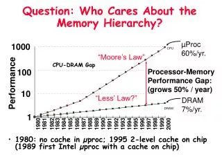
Understanding Memory Hierarchy: Cache and Virtual Memory in Computing
This chapter covers the principle of locality, memory hierarchy, and cache concepts integral to computer performance. Learn about temporal and spatial locality, their impact on memory organization, and how caches bridge the gap between CPU and main memory. Explore different cache organizations, including direct-mapped, set associative, and fully associative caches, along with key terms like hit rate, miss rate, and miss penalty. Gain insights into virtual memory concepts and their role in optimizing performance.

Understanding Memory Hierarchy: Cache and Virtual Memory in Computing
E N D
Presentation Transcript
CHAPTER 7LARGE AND FAST: EXPLOITING MEMORY HIERARCHY Topics to be covered • Principle of locality • Memory hierarchy • Cache concepts and cache organization • Virtual memory concepts • Impact of cache & virtual memories on performance S. Barua – CPSC 440 sbarua@fullerton.edu http://sbarua.ecs.fullerton.edu
PRINCIPLE OF LOCALITY Two types of locality inherent in programs are: • Temporal locality: Locality in time If an item is referenced, it will tend to be referenced again soon • Spatial locality: Locality in space If an item is referenced, items whose addresses are close by will tend to be referenced soon The principle of locality allows the implementation of memory hierarchy. S. Barua – CPSC 440 sbarua@fullerton.edu http://sbarua.ecs.fullerton.edu
MEMORY HIERARCHY • Consists of multiple levels of memory with different speeds and sizes. • Goal is to provide the user with memory at a low cost, while providing access at the speed offered by the fastest memory. S. Barua – CPSC 440 sbarua@fullerton.edu http://sbarua.ecs.fullerton.edu
MEMORY HIERARCHY (Continued) CPU Speed Size Cost/bit ImplementedUsing Cache Fastest Smallest Highest SRAM Memory Main DRAM Memory SecondarySlowest Biggest Lowest Magnetic Memory Disk Memory hierarchy in a computer S. Barua – CPSC 440 sbarua@fullerton.edu http://sbarua.ecs.fullerton.edu
CACHE MEMORY Cache represents the level of memory hierarchy between the main memory and the CPU. Terms associated with cache Hit:The item requested by the processor is found in some block in the cache. Miss:The item requested by the processor is not found in the cache. S. Barua – CPSC 440 sbarua@fullerton.edu http://sbarua.ecs.fullerton.edu
Terms associated with cache (Continued) Hit rate: The fraction of the memory access found in the cache. Used as a measure of performance of the cache. Hit rate = (Number of hits) Number of access = (Number of hits) (# hits + # misses) Miss rate: The fraction of memory access not found in cache. Miss rate = 1.0 - Hit rate S. Barua – CPSC 440 sbarua@fullerton.edu http://sbarua.ecs.fullerton.edu
Terms associated with cache (Continued) Hit time: Time to access the cache memory Includes the time needed to determine whether the access is a hit or miss. Miss penalty: Time to replace a cache block with the corresponding block from the memory the time to deliver this block to the processor S. Barua – CPSC 440 sbarua@fullerton.edu http://sbarua.ecs.fullerton.edu
Cache Organizations Three types of cache organizations available • Direct-mapped cache • Set associative cache • Fully associative cache S. Barua – CPSC 440 sbarua@fullerton.edu http://sbarua.ecs.fullerton.edu
DIRECT MAPPED CACHE Each main memory block is mapped to exactly one location in the cache.(It is assumed for right now that 1 block = 1word) For each block in the main memory, a corresponding cache location is assigned based on the address of the block in the main memory. Mapping used in a direct-mapped cache: Cache index = (Memory block address) modulo (Number of blocks in the cache) S. Barua – CPSC 440 sbarua@fullerton.edu http://sbarua.ecs.fullerton.edu
Example of a Direct-Mapped Cache Figure 7.5 A direct-mapped cache of 8 blocks S. Barua – CPSC 440 sbarua@fullerton.edu http://sbarua.ecs.fullerton.edu
Accessing a Cache Location and Identifying a Hit We need to know • Whether a cache block has valid information - done using valid bit and • Whether the cache block corresponds to the requested word - done using tags S. Barua – CPSC 440 sbarua@fullerton.edu http://sbarua.ecs.fullerton.edu
CONTENTS OF A CACHE MEMORY BLOCK A cache memory block consists of the data bits, tag bits and a valid (V)bit. V bit is set only if the cache block has valid information. CacheV Tag Data index S. Barua – CPSC 440 sbarua@fullerton.edu http://sbarua.ecs.fullerton.edu
CACHE AND MAIN MEMORY STRUCTURE CacheMemory index V Tag Block address Data 0 0 1 1 2 Block (K words) K-1 Block length (K words) Word length S. Barua – CPSC 440 sbarua@fullerton.edu http://sbarua.ecs.fullerton.edu
CACHE CONCEPT CPU Word transfer Cache Block transfer Main Memory S. Barua – CPSC 440 sbarua@fullerton.edu http://sbarua.ecs.fullerton.edu
IDENTIFYING A CACHE HIT The index of a cache block and the tag contents of that block uniquely specify the memory address of the word contained in the cache block. Example: Consider a 32-bit memory address and a cache block size of one word. The cache has 1024 words. Compute the following. Cache index = ? bits Byte offset = ? bits Tag = ? bits Actual cache size = ? bits S. Barua – CPSC 440 sbarua@fullerton.edu http://sbarua.ecs.fullerton.edu
Example (Continued) Figure. 7.7 Identifying a hit on the cache block S. Barua – CPSC 440 sbarua@fullerton.edu http://sbarua.ecs.fullerton.edu
A Cache Example The series of memory address references given as word addresses are 22, 26, 22, 26, 16, 3, 16, and 18. Assume a direct-mapped cache with 8 one-word blocks that is initially empty. Label each reference in the list as a hit or miss and show the contents of the cache after each reference. S. Barua – CPSC 440 sbarua@fullerton.edu http://sbarua.ecs.fullerton.edu
A Cache Example (Continued) Index V Tag DataIndex V Tag Data 000 000 001 001 010 010 011 (a) 011 (b) 100 100 101 101 110 110 111 111 Initial state of the cache S. Barua – CPSC 440 sbarua@fullerton.edu http://sbarua.ecs.fullerton.edu
A Cache Example (Continued) Index V Tag Data Index V Tag Data 000 000 001 001 010 010 011 (c) 011 (d) 100 100 101 101 110 110 111 111 S. Barua – CPSC 440 sbarua@fullerton.edu http://sbarua.ecs.fullerton.edu
A Cache Example (Continued) Index V Tag Data Index V Tag Data 000 000 001 001 010 010 011 (e) 011 (f) 100 100 101 101 110 110 111 111 S. Barua – CPSC 440 sbarua@fullerton.edu http://sbarua.ecs.fullerton.edu
HANDLING CACHE MISSES If the cache reports a miss, then the corresponding block has to be loaded into the cache from the main memory. • The requested word may be forwarded immediately to the processor as the block is being updated or • The requested word may be delayed until the entire block has been stored in the cache S. Barua – CPSC 440 sbarua@fullerton.edu http://sbarua.ecs.fullerton.edu
HANDLING CACHE MISSES FOR INSTRUCTIONS • Decrement PC by 4 • Fetch the block containing the missed instruction from the main memoryand write the block into the cache • Write the instruction block into the data portion of the referenced cache block • Copy the upper bits of the referenced memory address into the tag field of the cache memory • Turn the valid (V) bit on • Restart the fetch cycle - this will refetch the instruction, this time finding it in cache S. Barua – CPSC 440 sbarua@fullerton.edu http://sbarua.ecs.fullerton.edu
HANDLING CACHE MISSES FOR DATA • Read the block containing the missed data from the main memoryand write the block into the cache • Write the data into the data portion of the referenced cache block • Copy the upper bits of the referenced memory address into the tag field of the cache memory • Turn the valid (V) bit on • The requested word may be forwarded immediately to the processor as the block is being updated or • The requested word may be delayed until the entire block has been stored in the cache S. Barua – CPSC 440 sbarua@fullerton.edu http://sbarua.ecs.fullerton.edu
CACHE WRITE POLICIES Two techniques used in handling a write to a cache block in response to a cache write miss: • Write-through Technique Updates both the cache and the main memory for each write • Write-back Technique Writes to cache only and postpones updating the main memory until the block is replaced in the cache S. Barua – CPSC 440 sbarua@fullerton.edu http://sbarua.ecs.fullerton.edu
CACHE WRITE POLICIES (Continued) The write-back strategy usually employs a “dirty bit” associated with each cache block, much the same as the valid bit. • The dirty bit will be set the first time a value is written to the block. • When a block in the cache is to be replaced, its dirty bit is examined. • If the dirty bit has been set, the block is written back to the main memory • otherwise it is simply overwritten. S. Barua – CPSC 440 sbarua@fullerton.edu http://sbarua.ecs.fullerton.edu
TAKING ADVANTAGE OF SPATIAL LOCALITY To take advantage of the spatial locality we should have a block that is larger than one word in length (multiple-word block). When a miss occurs, the entire block (consisting of multiple words that are adjacent) will be fetched from the main memory and brought into cache. The total number of tags and valid bits, in a cache with multiword block, is less because each tag and valid bit are used for several words. S. Barua – CPSC 440 sbarua@fullerton.edu http://sbarua.ecs.fullerton.edu
Cache with Multiple-word Blocks - Example Figure 7.9 A 16 KB cache using 16-word blocks S. Barua – CPSC 440 sbarua@fullerton.edu http://sbarua.ecs.fullerton.edu
Identifying a Cache Block for a Given Memory Address For a given memory address, the corresponding cache block can be determined as follows: Step 1: Identify the memory block that contains the given memory address Memory block address = (Word address) div (Number of words in the block)Memory block address = (Byte address) div (Number of bytes in the block) (Memory block address is essentially the block number in the main memory.) Step 2: Compute the cache index corresponding to the memory block Cache block address = (Memory Block address) Modulo (Number of blocks in cache) S. Barua – CPSC 440 sbarua@fullerton.edu http://sbarua.ecs.fullerton.edu
HANDLING CACHE MISSES FOR A MULTIWORD BLOCK For a cache read miss, the corresponding block is copied into the cache from the memory. A cache write miss, in a multiword block cache, is handled in two steps: • Step 1: Copy the corresponding block from memory into cache • Step 2: Update the cache block with the requested word S. Barua – CPSC 440 sbarua@fullerton.edu http://sbarua.ecs.fullerton.edu
EFFECT OF A LARGER BLOCK SIZE ON PERFORMANCE In general, the miss rate falls when we increase the block size. • The miss rate may actually go up, if the block size is made very large compared with the cache size, due to the following reasons: • The number of blocks that can be held in the cache will become small, giving rise to a great deal of competition for these blocks. • A block may be bumped out of the cache before many of its words can be used. • Increasing the block size increases the cost of a miss (miss penalty) S. Barua – CPSC 440 sbarua@fullerton.edu http://sbarua.ecs.fullerton.edu
DESIGNING MEMORY SYSTEMS TO SUPPORT CACHES Three memory organizations are widely used: • One-word-wide memory organization • Wide memory organization • Interleaved memory organization Figure 7.11 Three options for designing the memory system S. Barua – CPSC 440 sbarua@fullerton.edu http://sbarua.ecs.fullerton.edu
Figure 7.11 Three options for designing the memory system S. Barua – CPSC 440 sbarua@fullerton.edu http://sbarua.ecs.fullerton.edu
Example Consider the following memory access times: 1 clock cycle to send the address 10 clock cycles for each DRAM access initiated 1 clock cycle to send a word of data Assume we have a cache block of four words. Discuss the impact of the different organizations on miss penalty and bandwidth per miss. S. Barua – CPSC 440 sbarua@fullerton.edu http://sbarua.ecs.fullerton.edu
MEASURING AND IMPROVING CACHE PERFORMANCE Total cycles CPU spends on a program equals: (Clock cycles CPU spends executing the program) + (Clock cycles CPU spends waiting for the memory system) Total CPU time = Total CPU cycles * Clock cycle time = (CPU execution clock cycles + Memory-stall clock cycles) * Clock cycle time S. Barua – CPSC 440 sbarua@fullerton.edu http://sbarua.ecs.fullerton.edu
MEASURING AND IMPROVING CACHE PERFORMANCE (Continued) Memory-stall clock cycles = Read-stall cycles + Write-stall cycles Read-stall cycles = Number of reads * Read miss rate * Read miss penalty Write-stall cycles = Number of writes * Write miss rate * Write miss penalty Total memory access = Number of reads + Number of writes Therefore, Memory-stall cycles = Total memory accesses* Miss rate * Miss penalty S. Barua – CPSC 440 sbarua@fullerton.edu http://sbarua.ecs.fullerton.edu
MEASURING AND IMPROVING CACHE PERFORMANCE Two ways of improving cache performance: • Decreasing the cache miss rate • Decreasing the cache miss penalty S. Barua – CPSC 440 sbarua@fullerton.edu http://sbarua.ecs.fullerton.edu
Example Assume the following: Instruction cache miss rate for gcc = 5% Data cache miss rate for gcc = 10% If a machine has a CPI of 4 without memory stalls and a miss penalty of 12 cycles for all misses, determine how much faster a machine would run with a perfect cache that never missed. The frequency of data transfer instructions in gcc is 33%. S. Barua – CPSC 440 sbarua@fullerton.edu http://sbarua.ecs.fullerton.edu
REDUCING CACHE MISSES BY MORE FLEXIBLE PLACEMENT OF BLOCKS Direct Mapped Cache: A block could go in exactly one place Set Associative Cache: There are a fixed number of locations where each block can be placed. • Each block in the memory maps to a unique set in the cache given by the index field. • A block can be placed in any element of that set. The set corresponding to a memory block is given by: Cache set # = (Block address) modulo (Number of sets in the cache) A set associative cache with n possible locations for a block is called an n-way set associative cache. S. Barua – CPSC 440 sbarua@fullerton.edu http://sbarua.ecs.fullerton.edu
REDUCING CACHE MISSES BY MORE FLEXIBLE PLACEMENT OF BLOCKS (Continued) Fully Associative Cache: A block can be placed in any location in the cache. To find a block in a fully associative cache, all the entries (blocks) in the cache must be searched Figure 7.14: Examples of direct-mapped, set associative and fully associative caches The miss rate decreases with the increase in the degree of associativity. S. Barua – CPSC 440 sbarua@fullerton.edu http://sbarua.ecs.fullerton.edu
Figure 7.14: Examples of direct-mapped, set associative and fully associative caches S. Barua – CPSC 440 sbarua@fullerton.edu http://sbarua.ecs.fullerton.edu
LOCATING A BLOCK IN THE CACHE Fig. 7.17: Locating a block in a four-way set associative cache S. Barua – CPSC 440 sbarua@fullerton.edu http://sbarua.ecs.fullerton.edu
CHOOSING WHICH BLOCK TO REPLACE Direct-mapped Cache When a miss occurs, the requested block can go in exactly one position. So the block occupying that position must be replaced. S. Barua – CPSC 440 sbarua@fullerton.edu http://sbarua.ecs.fullerton.edu
CHOOSING WHICH BLOCK TO REPLACE (Continued) Set associative or fully associative Cache When a miss occurs we have a choice of where to place the requested block, and therefore a choice of which block to replace. • Set associative cache: All the blocks in the selected set are candidates for replacement. • Fully associative cache: All blocks in the cache are candidates for replacement. S. Barua – CPSC 440 sbarua@fullerton.edu http://sbarua.ecs.fullerton.edu
Replacing a Block in Set Associative and Fully Associative Caches Strategies employed are: • First-in-first-out (FIFO): The block replace is the one that was brought in in first • Least-frequently used (LFU): The block replaced is the one that is least frequently used • Random: Blocks to be replaced are randomly selected • Least Recently Used (LRU): The block replaced is the one that has been unused for the longest time. LRU is the most commonly used replacement technique. S. Barua – CPSC 440 sbarua@fullerton.edu http://sbarua.ecs.fullerton.edu
REDUCING THE MISS PENALTY USING MULTILEVEL CACHES To further close the gap between the fast clock rates of modern processors and the relatively long time required to access DRAMs, high-performance microprocessors support an additional level of caching. This second-level cache (often off chip in a separate set of SRAMs) will be accessed whenever a miss occurs in the primary cache. Since the access time for the second-level cache is significantly less than the access time of the main memory, the miss penalty of the primary cache is greatly reduced. S. Barua – CPSC 440 sbarua@fullerton.edu http://sbarua.ecs.fullerton.edu
Evolution of Cache organization 80386:No on-chip cache. Employs a direct-mapped external cache with a block size of 16 bytes (4, 32-bit words). Employs write-through technique. 80486: Has a single on-chip cache of 8 KByte with a block size of 16 bytes and a 4-way set associative organization. Employs write-through technique and LRU replacement algorithm. Pentium/Pentium Pro: Employs split instruction and data caches (2 on-chip caches, one for data and one for instructions). Each cache is 8 KByte with a block size of 32 bytes and a 4-way set associative organization. Employs a write-back policy and the LRU replacement algorithm. Supports the use of a 2-way set associative level 2 cache of 256 or 512 Kbytes with a block size of 32, 64, or 128 bytes. Employs a write-back policy and the LRU replacement algorithm. Can be dynamically configured to support write-through caching. In Pentium Pro, the secondary cache is on a separate die, but packaged together with the processor. S. Barua – CPSC 440 sbarua@fullerton.edu http://sbarua.ecs.fullerton.edu
Evolution of Cache organization (Continued) Pentium II:Employs split instruction and data caches. Each cache is 16 Kbytes. Supports the use of a level 2 cache of 512 Kbytes. PII Xeon: Employs split instruction and data caches. Each cache is 16 Kbytes. Supports the use of a level 2 cache of 1 Mbytes or 2 Mbytes. Celeron: Employs split instruction and data caches. Each cache is 16 Kbytes. Supports the use of a level 2 cache of 128 Kbytes. Pentium III: Employs split instruction and data caches. Each cache is 16 Kbytes. Supports the use of a level 2 cache of 512 Kbytes. S. Barua – CPSC 440 sbarua@fullerton.edu http://sbarua.ecs.fullerton.edu
Evolution of Cache Organization (Continued) Pentium 4: Employs split instruction and data caches (2 on-chip caches, one for data and one for instructions). Each cache is 8 KByte with a block size of 64 bytes and a 4-way set associative organization. Employs a write-back policy and the LRU replacement algorithm. Supports the use of a 2-way set associative level 2 cache of 256 Kbytes with a block size of 128 bytes. Employs a write-back policy and the LRU replacement algorithm. Can be dynamically configured to support write-through caching. S. Barua – CPSC 440 sbarua@fullerton.edu http://sbarua.ecs.fullerton.edu
Evolution of Cache organization (Continued) Power PC: Model 601 has a single on-chip 32 Kbytes, 8-way set associative cache with a block size of 32 bytes. Model 603 has two on-chip 8 Kbytes, 2-way set associative caches with a block size of 32 bytes. Model 604 has two on-chip 16 KByte, 4-way set associative caches with a block size of 32 bytes. Uses LRU replacement algorithm and write-through and write-back techniques. Employs a 2-way set associative level 2 cache of 256 or 512 Kbytes with a block size of 32 bytes. Model 620 has two on-chip 32 Kbytes, 8-way set associative caches with a block size of 64 bytes. Model G3 has two on-chip 32 Kbytes, 8-way set associative caches with a block size of 64 bytes. Model G4 has two on-chip 32 Kbytes, 8-way set associative caches with a block size of 32 bytes S. Barua – CPSC 440 sbarua@fullerton.edu http://sbarua.ecs.fullerton.edu
ELEMENTS OF CACHE DESIGN The key elements that serve to classify and differentiate cache architectures are as follows: • Cache size • Mapping function • Direct • Set associative • Fully associative • Replacement algorithms (for set and fully associative) • Least-recently used (LRU) • First-in-first-out (FIFO) • Least-frequently used (LFU) • Random • Write policy • Write-through • Write-back • Block size • Number of caches • Single-level or two-level • Unified or split S. Barua – CPSC 440 sbarua@fullerton.edu http://sbarua.ecs.fullerton.edu